Sharp AR-M237 AR-M237 AR-M277 Operation Manual Suite - Page 124
Parts Of The Machine
 |
View all Sharp AR-M237 manuals
Add to My Manuals
Save this manual to your list of manuals |
Page 124 highlights
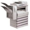
BEFORE USING THE FAX FEATURE PARTS OF THE MACHINE 12 3 4 11 5 6 7 13 8 12 9 10 1 Exit area The original exits here after transmission or scanning into memory. 2 Document feeder tray Place the original face-up in this tray for transmission.(p.10) 3 Original guides Adjust these guides to match the width of the original.(p.10) 4 Document glass Books and other originals that cannot be inserted into the RSPF can be placed here.(p.10) 5 Operation panel (p.5) 6 Job separator tray Received faxes are delivered to this tray. Fax function lists are also delivered here after printing. *The job separator tray cannot be used when a finisher is installed. Also, the output tray can be changed using a key operator program for the copy function. See "OUTPUT TRAYS" in the key operator's guide. 7 Center tray The output tray for received faxes can be changed to the center tray using the key operator programs for the copy function. 6 8 Front cover Open this cover to remove a misfeed. (See the operation manual for copier.) 9 Paper trays These hold the paper that is used for fax reception and copying. Each tray holds approximately 500 sheets of paper. (See the operation manual for copier.) 10 Power switch Turns the power on and off.(p.3) 11 Speaker The line can be heard through the speaker during on-hook dialing, as well as the beep that signals the completion of a fax transmission. 12 LINE jack Insert the telephone line cord here.(p.3) 13 TEL jack Connect an extension telephone here.(p.61) Note For parts of the machine that are related to both faxing and copying (parts related to removing misfeeds, loading paper, etc.), see "PART NAMES AND FUNCTIONS" in the operation manual for copier.
-
 1
1 -
2
-
3
-
4
-
5
-
6
-
7
-
8
-
9
-
10
-
11
-
12
-
13
-
14
-
15
-
16
-
17
-
18
-
19
-
20
-
21
-
22
-
23
-
24
-
25
-
26
-
27
-
28
-
29
-
30
-
31
-
32
-
33
-
34
-
35
-
36
-
37
-
38
-
39
-
40
-
41
-
42
-
43
-
44
-
45
-
46
-
47
-
48
-
49
-
50
-
51
-
52
-
53
-
54
-
55
-
56
-
57
-
58
-
59
-
60
-
61
-
62
-
63
-
64
-
65
-
66
-
67
-
68
-
69
-
70
-
71
-
72
-
73
-
74
-
75
-
76
-
77
-
78
-
79
-
80
-
81
-
82
-
83
-
84
-
85
-
86
-
87
-
88
-
89
-
90
-
91
-
92
-
93
-
94
-
95
-
96
-
97
-
98
-
99
-
100
-
101
-
102
-
103
-
104
-
105
-
106
-
107
-
108
-
109
-
110
-
111
-
112
-
113
-
114
-
115
-
116
-
117
-
118
-
 119
119 -
 120
120 -
 121
121 -
 122
122 -
 123
123 -
 124
124 -
 125
125 -
 126
126 -
 127
127 -
 128
128 -
 129
129 -
130
-
131
-
132
-
133
-
134
-
135
-
136
-
137
-
138
-
139
-
140
-
141
-
142
-
143
-
144
-
145
-
146
-
147
-
148
-
149
-
150
-
151
-
152
-
153
-
154
-
155
-
156
-
157
-
158
-
159
-
160
-
161
-
162
-
163
-
164
-
165
-
166
-
167
-
168
-
169
-
170
-
171
-
172
-
173
-
174
-
175
-
176
-
177
-
178
-
179
-
180
-
181
-
182
-
183
-
184
-
185
-
186
-
187
-
188
-
189
-
190
-
191
-
192
-
193
-
194
-
195
-
196
-
197
-
198
-
199
-
200
-
201
-
202
-
203
-
204
-
205
-
206
-
207
-
208
-
209
-
210
-
211
-
212
-
213
-
214
-
215
-
216
-
217
-
218
-
219
-
220
-
221
-
222
-
223
-
224
-
225
-
226
-
227
-
228
-
229
-
230
-
231
-
232
-
233
-
234
-
235
-
236
-
237
-
238
-
239
-
240
-
241
-
242
-
243
-
244
-
245
-
246
-
247
-
248
-
249
-
250
-
251
-
252
-
253
-
254
-
255
-
256
-
257
-
258
-
259
-
260
-
261
-
262
-
263
 |
 |
