Toshiba Satellite Pro 4300 User Manual - Page 139
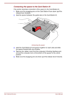
Computer connector, Finger grips, Guide rails, Metal latches, Eject lever release, button
 |
View all Toshiba Satellite Pro 4300 manuals
Add to My Manuals
Save this manual to your list of manuals |
Page 139 highlights
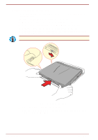
Front The illustration below shows the Port Replicator's front. ENGAGING PIN (NOT SHOWN) METAL LATCHES COMPUTER CONNECTOR ENGAGING PIN (NOT SHOWN) FINGER GRIP GUIDE RAILS EJECT LEVER RELEASE BUTTON VOLUME CONTROL EJECT LEVER FINGER GRIP The front Computer connector This is the computer interface. It connects directly to the computer's docking interface port. Finger grips Use these grips to steady the Port Replicator as you push the computer forward with your thumbs. Guide rails These rails guide the computer to a proper connection with the Port Replicator. Metal latches These latches engage slots on the bottom of the computer to hold it securely to the Port Replicator. Eject lever release button Press this button when you pull the elect lever to disconnect the Port Replicator. Engaging pins These pins engage holes on the computer to secure the connection. User's Manual Optional Devices 8-27
-
 1
1 -
2
-
3
-
4
-
5
-
6
-
7
-
8
-
9
-
10
-
11
-
12
-
13
-
14
-
15
-
16
-
17
-
18
-
19
-
20
-
21
-
22
-
23
-
24
-
25
-
26
-
27
-
28
-
29
-
30
-
31
-
32
-
33
-
34
-
35
-
36
-
37
-
38
-
39
-
40
-
41
-
42
-
43
-
44
-
45
-
46
-
47
-
48
-
49
-
50
-
51
-
52
-
53
-
54
-
55
-
56
-
57
-
58
-
59
-
60
-
61
-
62
-
63
-
64
-
65
-
66
-
67
-
68
-
69
-
70
-
71
-
72
-
73
-
74
-
75
-
76
-
77
-
78
-
79
-
80
-
81
-
82
-
83
-
84
-
85
-
86
-
87
-
88
-
89
-
90
-
91
-
92
-
93
-
94
-
95
-
96
-
97
-
98
-
99
-
100
-
101
-
102
-
103
-
104
-
105
-
106
-
107
-
108
-
109
-
110
-
111
-
112
-
113
-
114
-
115
-
116
-
117
-
118
-
119
-
120
-
121
-
122
-
123
-
124
-
125
-
126
-
127
-
128
-
129
-
130
-
131
-
132
-
133
-
 134
134 -
 135
135 -
 136
136 -
 137
137 -
 138
138 -
 139
139 -
 140
140 -
 141
141 -
 142
142 -
 143
143 -
 144
144 -
145
-
146
-
147
-
148
-
149
-
150
-
151
-
152
-
153
-
154
-
155
-
156
-
157
-
158
-
159
-
160
-
161
-
162
-
163
-
164
-
165
-
166
-
167
-
168
-
169
-
170
-
171
-
172
-
173
-
174
-
175
-
176
-
177
-
178
-
179
-
180
-
181
-
182
-
183
-
184
-
185
-
186
-
187
-
188
-
189
-
190
-
191
-
192
-
193
-
194
-
195
-
196
-
197
-
198
-
199
-
200
-
201
-
202
-
203
-
204
-
205
-
206
-
207
-
208
-
209
-
210
-
211
-
212
-
213
-
214
-
215
-
216
-
217
-
218
-
219
-
220
-
221
-
222
-
223
-
224
-
225
-
226
-
227
-
228
-
229
-
230
 |
 |
