Yamaha DME32 DME32 Owners Manual
Yamaha DME32 Manual
 |
View all Yamaha DME32 manuals
Add to My Manuals
Save this manual to your list of manuals |
Yamaha DME32 manual content summary:
- Yamaha DME32 | DME32 Owners Manual - Page 1
LOCK EMERGENCY CONFIGURATION SCENE XXXXXYAMAHAXDME32 XDigitalXMixingXEngine COMPONENT PARAMETER VALUE PROTECT UTILITY CARD DATA USER DEFINE INC DEC SCENE RECALL 7 8 9 4 5 6 1 2 3 STORE 0 RECALL POWER ON OFF DIGITAL MIXING ENGINE Keep This Manual For Future Reference. E - Yamaha DME32 | DME32 Owners Manual - Page 2
instructions contained in this manual, meets FCC requirements. Modifications not expressly approved by Yamaha "ON", please try to eliminate the problem by using one of the following measures: afdankt of de volgende Yamaha Service Afdeiing: Yamaha Music Nederland Service Afdeiing Kanaalweg 18-G, 3526 - Yamaha DME32 | DME32 Owners Manual - Page 3
only to an AC outlet of the type stated in this Owner's Manual or as marked on the DME32. Failure to do so is a fire and electrical shock hazard. you continue using the DME32 without heeding this instruction, fire or electrical shock may result. • Do not remove the DME32's cover. You could receive - Yamaha DME32 | DME32 Owners Manual - Page 4
DME32, and use only the cables specified in the relevant owner's manuals. • If you plan not to use the DME32 DME32 uses high-frequency digital circuits that may cause interference on radio and television equipment located nearby. If interference is a problem, relocate the affected equipment. DME32 - Yamaha DME32 | DME32 Owners Manual - Page 5
. Contact your Yamaha dealer if you are missing an item. • DME32 Digital Mixing Engine • CD-ROM (DME Manager software) • 9-pin D-sub crossed cable (PC connection) • 16-pin Euro-block plug (GPI interface) • Power cord • This manual Trademarks ADAT MultiChannel Optical Digital Interface is a trademark - Yamaha DME32 | DME32 Owners Manual - Page 6
DME Manager 12 Starting DME Manager 12 Quitting DME Manager 13 DME Manager & Windows 13 Installing the USB Driver 13 Checking the Driver is Installed Correctly 14 USB Operating Notes 14 3 Touring the DME32 15 Front Panel 16 Rear Panel 19 4 Touring DME Manager 21 Modes 22 Main Window 23 - Yamaha DME32 | DME32 Owners Manual - Page 7
Compiling Configurations 61 Sending Configurations to the DME32 62 Receiving Configurations from the DME32 63 6 Running the System 65 Protection 83 Assigning the User Define Button 86 Printing 87 8 Component Guide Part I 89 Automatic Mixer 90 Cascade 92 Crossover 93 Crossover Processor - Yamaha DME32 | DME32 Owners Manual - Page 8
236 Multiple-Unit System Notes 236 Cascade Connections 237 Multiple-unit Hookup Examples 238 15 MIDI 241 MIDI & the DME32 242 MIDI Ports 242 MIDI Settings 242 Assigning Scenes & Configurations to Program Changes 244 Assigning Component Parameters to Control Changes 246 DME32-Owner's Manual - Yamaha DME32 | DME32 Owners Manual - Page 9
DME32 252 I/O Card Specifications 253 Choosing I/O Cards 253 Installing I/O Cards 255 AD824 & DA824 Converters 256 Troubleshooting 261 DME32 261 DME Manager 263 Appendix A: General 265 Component Title Table 265 DME32 Pin Assignments 274 DME32 Dimensions 277 - Yamaha DME32 | DME32 Owners Manual - Page 10
Welcome 1 Welcome 1 In this chapter... Welcome 2 The DME32 in a Nutshell 2 DME32 Features 4 DME Manager Features 6 About this Manual 7 Installing the DME32 7 DME32-Owner's Manual - Yamaha DME32 | DME32 Owners Manual - Page 11
2 Chapter 1-Welcome Welcome Thank you for choosing the Yamaha DME32 Digital Mixing Engine. The DME32 Digital Mixing Engine and DME Manager software allow sound-system installers to custom build systems to meet the specific requirements of almost any installation. Entire systems from input through - Yamaha DME32 | DME32 Owners Manual - Page 12
password protection. The DME32 offers 32 inputs and 32 outputs via four mini YGDAI card slots. Optional mini YGDAI (Yamaha General Digital Audio Interface) cards offer a variety of analog and digital I/O configurations, with support for all the popular digital audio interconnect formats, including - Yamaha DME32 | DME32 Owners Manual - Page 13
• Optional mini YGDAI cards offer a variety of analog and digital I/O configurations, with support for all the popular digital audio interconnect formats, including AES/EBU, ADAT, and Tascam TDIF-1. • Analog I/O options include the Yamaha AD824 8-channel 24-bit A/D converter and DA824 8-channel 24 - Yamaha DME32 | DME32 Owners Manual - Page 14
• Assignable [USER DEFINE] button for quick parameter access Others • Large, 2-digit scene number indicator • 48-character LCD display • Password protection prevents unauthorized operation • Wordclock I/O and switchable termination for master/slave operation • 3U rack space DME32-Owner's Manual - Yamaha DME32 | DME32 Owners Manual - Page 15
recall and store scenes, and recall configurations • Actions performed on DME Manager are reflected on the DME32 and vice versa Offline Operation • Build and edit configurations off-site • Edit, title, and delete Floating tool palette and Alt-click mode menu for quick mode switching DME32-Owner's Manual - Yamaha DME32 | DME32 Owners Manual - Page 16
and locate topics. Use the index to locate specific information. A glossary of DME32-related jargon is provided on page 287. In this manual, the DME32 Digital Mixing Engine and DME Manager software are referred to as the "DME32" and "DME Manager" respectively. "PC" refers to an IBM PC-compatible - Yamaha DME32 | DME32 Owners Manual - Page 17
11 Turning On & Off the DME32 11 Installing DME Manager 12 Upgrading & Reinstalling DME Manager 12 Starting DME Manager 12 Quitting DME Manager 13 DME Manager & Windows 13 Installing the USB Driver 13 Checking the Driver is Installed Correctly 14 USB Operating Notes 14 DME32-Owner's Manual - Yamaha DME32 | DME32 Owners Manual - Page 18
The DME32 can be connected to a PC by using standard RS232/RS422 serial connections or USB (Universal Serial Bus). When the DME32 receives therefore supports longer cable lengths. RS232 supports cable lengths of up to 15 meters, while RS422 supports OUT GND 1 SLOT COM port DME32-Owner's Manual - Yamaha DME32 | DME32 Owners Manual - Page 19
RECALL POWER ON OFF DIGITAL MIXING ENGINE USB port USB cable USB port Connecting the Power Cord AC IN Warning: Turn off all equipment before making any power connections. Connect the socket-end of the supplied power cord to the AC IN socket on the rear panel of the DME32. Connect the plug-end - Yamaha DME32 | DME32 Owners Manual - Page 20
x 480, 256 color minimum) • An RS232 or RS422 serial port or a USB port • Windows 95/98 Installing DME Manager Before installing DME Manager, make sure that the installation manually, as explained below. 4 Double-click the My Computer icon. The My Computer window opens. 5 Double-click the "DME32" CD- - Yamaha DME32 | DME32 Owners Manual - Page 21
If components and wires are displayed out of alignment, you can resolve the problem as follows: in Windows 98, open the Display control panel, click the PC. Installing the USB Driver In order to use the USB port, you must install the USB driver as follows. For this you'll need your DME32 CD-ROM, and - Yamaha DME32 | DME32 Owners Manual - Page 22
. 3 Check to see if "YAMAHA USB MIDI Driver" appears in the list, as shown right. If it does, the driver is installed correctly. 4 Click Cancel to close the Properties window. USB Operating Notes If you turn on or off the power to the DME32, or connect or disconnect the USB cable under the following - Yamaha DME32 | DME32 Owners Manual - Page 23
Touring the DME32 15 Touring the DME32 3 In this chapter... Front Panel 16 Rear Panel 19 DME32-Owner's Manual - Yamaha DME32 | DME32 Owners Manual - Page 24
4 5 6 1 2 3 STORE 0 RECALL POWER ON OFF DIGITAL MIXING ENGINE 9JKL MNO P Q R S T U V A SCENE NO. indicator This 2-digit display shows the number of the current scene memory. The number fl . Turn it clockwise to increase a value; counterclockwise to decrease it. DME32-Owner's Manual - Yamaha DME32 | DME32 Owners Manual - Page 25
information. L USB port This USB port is used to connect the DME32 to a Windows DME32" on page 203 for more information. P CARD slot Optional PC Card memory cards are inserted here for additional configuration and scene storage. See "PC Cards" on page 221 for more information. DME32-Owner's Manual - Yamaha DME32 | DME32 Owners Manual - Page 26
18 Chapter 3-Touring the DME32 Q CARD eject button This button is used to eject PC Cards. See " to the right. V POWER switch This switch is used to turn on the power to the DME32. See "Turning On & Off the DME32" on page 11 for more information. There are two M3 screw holes above and below the - Yamaha DME32 | DME32 Owners Manual - Page 27
M A AC IN connector This connector is used to connect the DME32 to an AC outlet, using the supplied power cord. See " to connect the DME32 with other MIDI equipment for remote See "MIDI & the DME32" on page 242 for This 9-pin D-sub connector is used to connect the DME32 to the serial port on a Windows PC. See - Yamaha DME32 | DME32 Owners Manual - Page 28
Interface" on page 211 for more information. M SLOTs 1-4 These four slots are for use with optional mini YGDAI cards, which offer a variety of analog and digital I/O options. See "I/O Options" on page 251 for more information. DME32-Owner's Manual - Yamaha DME32 | DME32 Owners Manual - Page 29
Windows 31 Run Mode Controller 33 Other Windows 33 Touring the Menus 34 Component List 40 Tool Palette 41 Alt Menu 41 Keyboard Shortcuts 42 DME32-Owner's Manual - Yamaha DME32 | DME32 Owners Manual - Page 30
51 for more information. Run Mode Run mode is used to control the DME32 system in real time, which includes editing component parameters, storing and recalling In Run mode, actions performed on DME Manager are reflected on the DME32 and vice versa. Components and wires cannot be edited in this mode. - Yamaha DME32 | DME32 Owners Manual - Page 31
guration window is selected, the title bar appears as follows. When the window for a configuration stored in the DME32 is selected, the configuration title is prefixed with the letter "A" or "B," as shown below. When the the title bar of the configuration window, not the main window. DME32-Owner's Manual - Yamaha DME32 | DME32 Owners Manual - Page 32
50 for more information. F Align This button aligns all components to the grid. See "Aligning Components to the Grid" on page 49 for more information. DME32-Owner's Manual - Yamaha DME32 | DME32 Owners Manual - Page 33
current configuration: Off, Component, or Operation. See "Using Password Protection" on page 83 for more information. E DME32 Status This section displays which configuration is currently selected on the DME32: "Config A" or "Config B." If no DME32 is available, "Offline" appears. DME32-Owner's Manual - Yamaha DME32 | DME32 Owners Manual - Page 34
using the commands in the control menu, which is accessed by clicking the program icon in the upper-left corner of the configuration window. DME32-Owner's Manual - Yamaha DME32 | DME32 Owners Manual - Page 35
amount of DSP processing power used by the configuration. There is one meter in each section of the configuration window, one for each DME32. Each meter starts at 0% and gradually rises as components are added. When the meter reaches 100%, all the DSP processing power has been used up - Yamaha DME32 | DME32 Owners Manual - Page 36
the Zoom command. The following configuration window shows a configuration zoomed to 150%. See "Zooming Configuration Windows" on page 50 for more information. DME32-Owner's Manual - Yamaha DME32 | DME32 Owners Manual - Page 37
Windows 29 Window Sections Each configuration window is divided into four sections, one for each DME32. Sections can be resized by dragging the boundary lines shown below. See "Resizing Sections of the Configuration Window" on page 59 for more information. Boundary lines DME32-Owner's Manual - Yamaha DME32 | DME32 Owners Manual - Page 38
configuration are the input and output components, like those shown below. These components represent the DME32's physical inputs and outputs. Components can be chosen from the Component menu, or dragged from the added component is suffixed with a number. For example, if a second DME32-Owner's Manual - Yamaha DME32 | DME32 Owners Manual - Page 39
, or by clicking, if it's a button or pop-up menu. When Cable mode is selected, the cursor changes to the cable tool, as shown below. DME32-Owner's Manual - Yamaha DME32 | DME32 Owners Manual - Page 40
functions, such as Save, OK, Cancel, and Enter. In addition to these, DME Manager also uses buttons to turn functions and parameters on and off. DME32-Owner's Manual - Yamaha DME32 | DME32 Owners Manual - Page 41
elsewhere. Run Mode Controller The Run Mode Controller appears when Run mode is selected. It's used to recall DME32 configurations and to store and recall scenes. See "Run Mode Controller" on page 67 for more is accessed by clicking the program icon in the upper-left corner. DME32-Owner's Manual - Yamaha DME32 | DME32 Owners Manual - Page 42
Saves the current configuration under a new name Closes the current configuration Prints the current configuration Sets up the printer Sends and receives DME32 configurations Opens the Scene Make window Compiles the current configuration Quits DME Manager See page 45 46 60 60 60 87 87 62 - Yamaha DME32 | DME32 Owners Manual - Page 43
the Run, Edit, and Cable modes. Command Run Edit Cable Description Selects Run mode Selects Edit mode Selects Cable mode See page 66 45 51 DME32-Owner's Manual - Yamaha DME32 | DME32 Owners Manual - Page 44
Opens the MIDI window Opens the Word Clock window Opens the Tool Palette Opens the Protection window See page 86 211 241 229 41 83 DME32-Owner's Manual - Yamaha DME32 | DME32 Owners Manual - Page 45
. Components can be selected from the menu and added to configurations. See page 47 for information on adding components to configurations. See "Component Guide Part I" on page 89 and "Component Guide Part II" on page 141 for detailed information on all the components. DME32-Owner's Manual - Yamaha DME32 | DME32 Owners Manual - Page 46
mark next to it, as shown above. The configuration windows corresponding to the configurations in the DME32 are prefixed with the letters "A" and "B." The currently running configuration is prefixed with the About command. The About command displays information about DME Manager. DME32-Owner's Manual - Yamaha DME32 | DME32 Owners Manual - Page 47
window for the selected component Opens the Module window 40 66 45 51 61 48, 51 48 48 48 48 49 48, 56 80 193 DME32-Owner's Manual - Yamaha DME32 | DME32 Owners Manual - Page 48
minus (-) symbol changes back to a plus (+) symbol. 5 To close the Component List, click the Close button in the upper-right corner. The Component List closes. DME32-Owner's Manual - Yamaha DME32 | DME32 Owners Manual - Page 49
below. 2 Choose a mode and then click. Command Run Edit Cable Description Selects Run mode Selects Edit mode Selects Cable mode See page 66 45 51 DME32-Owner's Manual - Yamaha DME32 | DME32 Owners Manual - Page 50
42 Chapter 4-Touring DME Manager Keyboard Shortcuts File Menu New Ctrl+N Open Ctrl+O Save Ctrl+S Print Ctrl+P Edit Menu Undo Cut Ctrl+Z Ctrl+X Copy Ctrl+C Paste Ctrl+V Duplicate Ctrl+D DME32-Owner's Manual - Yamaha DME32 | DME32 Owners Manual - Page 51
59 Saving Configurations 60 Saving Configurations under a New Name 60 Closing Configurations 60 Compiling Configurations 61 Sending Configurations to the DME32 62 Receiving Configurations from the DME32 63 DME32-Owner's Manual - Yamaha DME32 | DME32 Owners Manual - Page 52
. See "Compiling Configurations" on page 61. 7 Save the configuration. See "Saving Configurations" on page 60. 8 Transfer the configuration to the DME32. See "Sending Configurations to the DME32" on page 62. 9 Take the system for a run, creating scenes as necessary. See "Running the System" on page 65 - Yamaha DME32 | DME32 Owners Manual - Page 53
Tool Bar, Tool Palette, or Alt menu. "Edit" appears in the status bar. In Edit mode, active DME32s, active meaning connected and turned on, display the message "EDIT CONTROL." 2 To leave Edit mode, select another a configuration is saved, its title changes to the name specified. DME32-Owner's Manual - Yamaha DME32 | DME32 Owners Manual - Page 54
Configurations Opening Saved Configurations Previously saved configurations can be opened as follows. If your PC supports PC Cards, configurations stored on PC Cards can also be opened using this method. 1 scroll bars. See "Configuration Windows" on page 26 for more information. DME32-Owner's Manual - Yamaha DME32 | DME32 Owners Manual - Page 55
figuration. In addition to using the Component menu, components can be added by dragging them from the Component List. See "Component List" on page 40. DME32-Owner's Manual - Yamaha DME32 | DME32 Owners Manual - Page 56
in both the Edit and Shortcut menus. • Component appearance, size, color, title, and so on, can be customized. See "Customizing Component Properties" on page 80. DME32-Owner's Manual - Yamaha DME32 | DME32 Owners Manual - Page 57
, which appears in the Edit and Shortcut menus and on the Tool Bar. The following configuration window shows a typical grid with an even X/Y spacing. DME32-Owner's Manual - Yamaha DME32 | DME32 Owners Manual - Page 58
, the currently selected zoom setting has a check mark next to it, as shown below. The following configuration window shows a configuration zoomed to 150%. DME32-Owner's Manual - Yamaha DME32 | DME32 Owners Manual - Page 59
the status bar and the cursor changes to the cable tool, as shown below. In Cable mode, active DME32s, active meaning connected and turned on, display the message "EDIT CONTROL." 2 To leave Cable mode, select another below. 3 Drag the wire to the second node, as shown below. DME32-Owner's Manual - Yamaha DME32 | DME32 Owners Manual - Page 60
nodes, as shown below. The last wire addition can be undone by using the Undo command, which appears in both the Edit and Shortcut menus. DME32-Owner's Manual - Yamaha DME32 | DME32 Owners Manual - Page 61
, as shown below. 3 Drop the wires behind the nodes on the other component, as shown below. The wires appear between the nodes, as shown below. DME32-Owner's Manual - Yamaha DME32 | DME32 Owners Manual - Page 62
of the selected nodes to the top node of the other component, as shown below. A small box appears around the top node, as shown below. DME32-Owner's Manual - Yamaha DME32 | DME32 Owners Manual - Page 63
4 Drop the wires onto the top node. The wires appear between the nodes, as shown below. Adding Wires 55 DME32-Owner's Manual - Yamaha DME32 | DME32 Owners Manual - Page 64
appears highlighted. 2 Choose the Delete command from the Edit or Shortcut menu. The Shortcut menu is shown below. The wire is deleted, as shown below. DME32-Owner's Manual - Yamaha DME32 | DME32 Owners Manual - Page 65
the mouse. 2 Choose the Delete command from the Edit or Shortcut menu. The Shortcut menu is shown below. The wires are deleted, as shown below. DME32-Owner's Manual - Yamaha DME32 | DME32 Owners Manual - Page 66
figuration Window" on page 59 for more information. Components for each DME32 are placed in the corresponding section of the configuration window. Components example shows a configuration window with two DME32s. Signals can be distributed among DME32s by using the Cascade components. See "Cascade" - Yamaha DME32 | DME32 Owners Manual - Page 67
the cursor over a boundary line. The cursor changes to the resize arrows, as shown below. 2 Drag the boundary to its new position, as shown below. DME32-Owner's Manual - Yamaha DME32 | DME32 Owners Manual - Page 68
can be accessed by the Windows operating system. If your PC supports PC Cards, configurations can be saved to a PC Card and then loaded into the DME32 via its card slot. Note that configurations must be compiled Close button in the upper-right corner of the configuration window. DME32-Owner's Manual - Yamaha DME32 | DME32 Owners Manual - Page 69
DME32. Compiling translates the configuration into information that the DME32 can now be transferred to the DME32. If the compilation fails, a this case you should rectify the problem and try compiling again. Compiling must be compiled and transferred to the DME32 each time any changes are made to - Yamaha DME32 | DME32 Owners Manual - Page 70
appears, as shown below. 2 In the Mode section, click Send. 3 From the List, select the DME32 configuration memory to which you want to send the configuration. The List shows the titles of the con 6 Click Cancel to close the Data Transfer window. The Data Transfer window closes. DME32-Owner's Manual - Yamaha DME32 | DME32 Owners Manual - Page 71
section, click Receive. 3 From the List, select the DME32 configuration you want to receive. The List shows the titles of the configurations stored in the DME32. The title of the current configuration has a green close the Data Transfer window. The Data Transfer window closes. DME32-Owner's Manual - Yamaha DME32 | DME32 Owners Manual - Page 72
Running the System 65 Running the System 6 In this chapter... Selecting Run Mode 66 Run Mode Controller 67 Editing Component Parameters 69 Storing Scenes 70 Recalling Scenes 72 Recalling Configurations 74 DME32-Owner's Manual - Yamaha DME32 | DME32 Owners Manual - Page 73
when DME Manager is started. See "Starting DME Manager" on page 12 for more information. It can also be received manually. See "Receiving Configurations from the DME32" on page 63 for more information. When Run mode is selected with several configuration windows open, the configuration and scene of - Yamaha DME32 | DME32 Owners Manual - Page 74
appears automatically when Run mode is selected, is used to recall DME32 configurations and to store and recall scenes just like using the DME32 front panel. It appears only when Run mode is selected and selected configuration memory contains no data, this button is unavailable. DME32-Owner's Manual - Yamaha DME32 | DME32 Owners Manual - Page 75
is stored, "EDIT" disappears. This operates in exactly the same way as the scene edit dots on the DME32 display. See "Front Panel" on page 16 for more information. C Selector buttons These buttons are used to selected scene memory contains no data, this button is unavailable. DME32-Owner's Manual - Yamaha DME32 | DME32 Owners Manual - Page 76
both the DME32 and DME DME32. The DME32 display shows one parameter at a time. If the currently selected parameter on the DME32 the DME32 front panel, you'll and editing parameters from the DME32 front panel, see " the scene edit dots appear on the DME32 display. See "Scene Control" on page - Yamaha DME32 | DME32 Owners Manual - Page 77
eld. Scene titles can be up to 24 characters long, although only the first 16 characters appear on the DME32 display. 5 To cancel your selection, click Cancel. On the Run Mode Controller, the number and title of the , scenes cannot be stored due to insufficient memory in the DME32. DME32-Owner's Manual - Yamaha DME32 | DME32 Owners Manual - Page 78
. 6 Click OK. The Title Edit window closes and the selected scene is stored on the DME32. The number and title of the scene appears on the DME32 display, the Run Mode Controller, and the Scene List. The stored scene becomes the current scene and its number and title appear in the con - Yamaha DME32 | DME32 Owners Manual - Page 79
each method is explained separately. In a multiple-unit system, the selected scene is recalled on all DME32s via the cascade connections. Recalling Scenes from the Controller 1 Select Run mode. See "Selecting Run Mode the scene data, it retrieves it automatically from the DME32. DME32-Owner's Manual - Yamaha DME32 | DME32 Owners Manual - Page 80
appears on the DME32 display and the Run Mode Controller. The recalled scene becomes the current scene and its number and title appear in the configuration window's title bar. If DME Manager does not already have the scene data, it retrieves it automatically from the DME32. DME32-Owner's Manual - Yamaha DME32 | DME32 Owners Manual - Page 81
speaker damage. In a multiple-unit system, the selected configuration is recalled on all DME32s via the cascade connections. 1 Select Run mode. See "Selecting Run Mode" on page message "Receive data from DME32?" appears. Click OK to receive the configuration data from the DME32. DME32-Owner's Manual - Yamaha DME32 | DME32 Owners Manual - Page 82
Customizing Component Properties 80 Changing the Size of Rotary Controls & Sliders 82 Using Password Protection 83 Assigning the User Define Button 86 Printing 87 DME32-Owner's Manual - Yamaha DME32 | DME32 Owners Manual - Page 83
and previewed offline, with no DME32s connected. New configurations are created with bar. The scene is not recalled on any connected DME32s. 4 Edit the component parameters as required. 5 Click scene is stored. The scene is not stored on any connected DME32s. 6 To edit a scene's title, select it from - Yamaha DME32 | DME32 Owners Manual - Page 84
be up to 24 characters long, although only the first 16 characters appear on the DME32 display. The Title Edit window closes and the edited title appears in the scene list. . You must transfer the configuration to the DME32 for the scene edits to take effect. See "How to Build & Edit Confi - Yamaha DME32 | DME32 Owners Manual - Page 85
speaker systems. In multiple-unit systems, component parameters can be linked across DME32s. Different parameter link settings can be stored in each scene. 1 Choose guration window (i.e., the components for each DME32) and the Parameters section lists all the parameters available for that component - Yamaha DME32 | DME32 Owners Manual - Page 86
settings for each scene without having to keep opening and closing the Parameter Link window. You must compile and transfer the configuration to the DME32 for the parameter links to take effect. See "How to Build & Edit Configurations" on page 44 for more information - Yamaha DME32 | DME32 Owners Manual - Page 87
to save your settings, or click Cancel to leave them unchanged. The Properties window closes and the component appears in accordance with the Properties settings. DME32-Owner's Manual - Yamaha DME32 | DME32 Owners Manual - Page 88
the following table. Section Parameter Range Component Input Nodes Output 0-16 0-16 Description Sets the number of input nodes Sets the number of output nodes DME32-Owner's Manual - Yamaha DME32 | DME32 Owners Manual - Page 89
unchanged. The Properties window closes and the control appears at the selected size. Examples of large and small rotary controls and sliders are shown below. DME32-Owner's Manual - Yamaha DME32 | DME32 Owners Manual - Page 90
a new name Open new configuration windows Open saved configurations Send configurations to the DME32 Receive configurations from the DME32 Change mode (Edit, Cable, Run) Print Close configurations Zoom configuration windows Quit DME be edited. No Yes Yes No No No No Yes No Yes No Yes DME32-Owner's Manual - Yamaha DME32 | DME32 Owners Manual - Page 91
to enter the old password and then the new password. If you enter them correctly, the new password is set and the Protection window closes. DME32-Owner's Manual - Yamaha DME32 | DME32 Owners Manual - Page 92
correctly, the password is deleted and the Protection window closes. Forgotten Passwords? If you forget a password, enter "OVERRIDE" in order to bypass the protection function. DME32-Owner's Manual - Yamaha DME32 | DME32 Owners Manual - Page 93
1 2 Up to 15 characters Selects the DME32 whose [USER DEFINE] button is to be parameter to be assigned The text that appears on the DME32 display when its [USER DEFINE] button is pressed You must compile and transfer the configuration to the DME32 for the User Define Button settings to take effect. - Yamaha DME32 | DME32 Owners Manual - Page 94
appears. Specify the file name and folder where you want to save the print file, and then click OK, or click Cancel to cancel printing. DME32-Owner's Manual - Yamaha DME32 | DME32 Owners Manual - Page 95
Component Guide Part I 89 Component Guide Part I 8 In this chapter... Automatic Mixer 90 Cascade 92 Crossover 93 Crossover Processor 102 Delay 120 Delayed Mixer 122 Dynamics 125 DME32-Owner's Manual - Yamaha DME32 | DME32 Owners Manual - Page 96
90 Chapter 8-Component Guide Part I Automatic Mixer There are three components in the Automatic Mixer group, each with a single output and 2, 4, or 8 inputs. window features input channels and a master output section. When a channel is soloed, "SOLO OFF" changes to "SOLO ON." DME32-Owner's Manual - Yamaha DME32 | DME32 Owners Manual - Page 97
of acoustic feedback. The Gain Correct function automatically reduces the output level depending on the number of channels that are open, thereby reducing this risk. DME32-Owner's Manual - Yamaha DME32 | DME32 Owners Manual - Page 98
92 Chapter 8-Component Guide Part I Cascade Cascade components are used to share and distribute signals among DME32s in a multiple-unit system, much like the buses in a mixing console. There are 32 components in the Cascade group, providing 32 cascade channels. Cascade components consist of bus- - Yamaha DME32 | DME32 Owners Manual - Page 99
Gc, and Gc set to -6 dB, the filter is practically a Linkwitz-Riley filter. With Gc settings greater than -3 dB, boost occurs around the cutoff frequency. DME32-Owner's Manual - Yamaha DME32 | DME32 Owners Manual - Page 100
94 Chapter 8-Component Guide Part I 2-Way Crossovers A 2-way crossover splits the input signal into two frequency channels: high and low. Four slope types high. Note that the Gc controls (not shown here) appear only when an Adjustable Gc type SLOPE & TYPE filter is selected. DME32-Owner's Manual - Yamaha DME32 | DME32 Owners Manual - Page 101
Butterworth 48dB/oct Bessel 48dB/oct Linkwitz-Riley 12 dB/oct O O O O O O Slope 24 dB/oct 36 dB/oct O O O O O O O O O O O O O O O O O O O O O O O O O O - O - O - O - - - - - - - - 48 dB/oct O O O O O O O O O O O O O O O O O O O O DME32-Owner's Manual - Yamaha DME32 | DME32 Owners Manual - Page 102
96 Chapter 8-Component Guide Part I 3-Way Crossovers A 3-way crossover splits the input signal into three frequency channels: low, mid, and high. Four slope high. Note that the Gc controls (not shown here) appear only when an Adjustable Gc type SLOPE & TYPE filter is selected. DME32-Owner's Manual - Yamaha DME32 | DME32 Owners Manual - Page 103
and the Gc value is fixed as follows: Butterworth and Bessel: -3 dB, Linkwitz-Riley: -6 dB. 2. SLOPE & TYPE parameter values are listed in the following table. DME32-Owner's Manual - Yamaha DME32 | DME32 Owners Manual - Page 104
98 Chapter 8-Component Guide Part I The following table shows the SLOPE & TYPE 24 dB/oct 36 dB/oct O O O O O O O O O O O O O O O O O O O O O O O O O O - O - O - O - - - - - - - - 48 dB/oct O O O O O O O O O O O O O O O O O O O O DME32-Owner's Manual - Yamaha DME32 | DME32 Owners Manual - Page 105
high-mid, and "H" for high. Note that the Gc controls (not shown here) appear only when an Adjustable Gc type SLOPE & TYPE filter is selected. DME32-Owner's Manual - Yamaha DME32 | DME32 Owners Manual - Page 106
100 Chapter 8-Component Guide Part I Section Parameter Range Description INPUT Level MUTE -Infinity dB to 0.0 dB Adjusts the input signal follows: Butterworth and Bessel: -3 dB, Linkwitz-Riley: -6 dB. 2. SLOPE & TYPE parameter values are listed in the following table. DME32-Owner's Manual - Yamaha DME32 | DME32 Owners Manual - Page 107
Butterworth 48dB/oct Bessel 48dB/oct Linkwitz-Riley 12 dB/oct O O O O O O Slope 24 dB/oct 36 dB/oct O O O O O O O O O O O O O O O O O O O O O O O O O O - O - O - O - - - - - - - - 48 dB/oct O O O O O O O O O O O O O O O O O O O O DME32-Owner's Manual - Yamaha DME32 | DME32 Owners Manual - Page 108
102 Chapter 8-Component Guide Part I Crossover Processor There are three components in the Crossover Processor group: 2-Way, 3-Way, and 4-Way. Each processor consists of a , EQ, and COMP pages selected by clicking the tabs along the top of the control window, as shown below. DME32-Owner's Manual - Yamaha DME32 | DME32 Owners Manual - Page 109
, "FS" indicates the selected wordclock frequency, and "340 m/s" and "1,115.5 ft/s" are the speed of sound in meters and feet respectively (air temperature = 14˚C, 57.2˚F). DME32-Owner's Manual - Yamaha DME32 | DME32 Owners Manual - Page 110
104 Chapter 8-Component Guide Part I The parameter ranges for the Samples, Meters, and Feet settings are as follows: Delay Scale FS = 48 KHz settings graphically. A vertical dotted line indicates the crossover frequency of each channel: "L" for low and "H" for high. DME32-Owner's Manual - Yamaha DME32 | DME32 Owners Manual - Page 111
Description Adjusts the selectivity of each band Adjusts the frequency of each band Adjusts the gain of each band Turns the EQ on and off DME32-Owner's Manual - Yamaha DME32 | DME32 Owners Manual - Page 112
106 Chapter 8-Component Guide Part I Comp The COMP page features compressors for the high and low channels, with gain reduction (GR) meters, compressor 42.3 sec (fs = 48 kHz), 6 ms-46.0 sec (fs = 44.1 kHz) See page 128 for more general information on compressor parameters. DME32-Owner's Manual - Yamaha DME32 | DME32 Owners Manual - Page 113
signal -Infinity dB to 0.0 dB Adjusts the high output signal level ON/OFF Mutes the high output NOR/REV Inverts the high output signal DME32-Owner's Manual - Yamaha DME32 | DME32 Owners Manual - Page 114
108 Chapter 8-Component Guide Part I Delay The DELAY page features individual delays for the low, mid, and high channels. Delay times can be follows: Samples Meters Feet Delay Scale FS = 48 KHz 0-24000 samples 0.0-170.0 meters 0.0-557.8 feet FS = 44.1 kHz 0-22050 samples DME32-Owner's Manual - Yamaha DME32 | DME32 Owners Manual - Page 115
Butterworth, Bessel, and Linkwitz-Riley, the Gc setting is ignored and the Gc value is fixed as follows: Butterworth and Bessel: -3 dB, Linkwitz-Riley: -6 dB. DME32-Owner's Manual - Yamaha DME32 | DME32 Owners Manual - Page 116
110 Chapter 8-Component Guide Part I 3. SLOPE & TYPE parameter values are as follows: THRU (filter off) 6dB/oct 12dB/oct Adjustable Gc 12dB/oct Butterworth 12dB/oct of each band Adjusts the frequency of each band Adjusts the gain of each band Turns each EQ channel on and off DME32-Owner's Manual - Yamaha DME32 | DME32 Owners Manual - Page 117
on and off 1. 5 ms-42.3 sec (fs = 48 kHz), 6 ms-46.0 sec (fs = 44.1 kHz) See page 128 for more general information on compressor parameters. DME32-Owner's Manual - Yamaha DME32 | DME32 Owners Manual - Page 118
112 Chapter 8-Component Guide Part I 4-Way Processor The 4-Way Processor component splits the input signal into four frequency channels-high, high-mid, low-mid, 1, EQ 2, COMP 1, and COMP 2 pages selected by clicking the tabs along the top of the control window, as shown below. DME32-Owner's Manual - Yamaha DME32 | DME32 Owners Manual - Page 119
individual delays for the low, low-mid, high-mid, and high channels. Delay times can be specified in milliseconds or samples, meters, or feet. DME32-Owner's Manual - Yamaha DME32 | DME32 Owners Manual - Page 120
114 Chapter 8-Component Guide Part I The Delay parameters for all channels are explained in the following table. Section Parameter Range Description LOW, LOW the crossover frequency of each channel: "L" for low, "ML" for low-mid, "MH" for high-mid, and "H" for high. DME32-Owner's Manual - Yamaha DME32 | DME32 Owners Manual - Page 121
-Riley 18dB/oct Adjustable Gc 18dB/oct Butterworth 18dB/oct Bessel 24dB/oct Adjustable Gc 24dB/oct Butterworth 24dB/oct Bessel 24dB/oct Linkwitz-Riley DME32-Owner's Manual - Yamaha DME32 | DME32 Owners Manual - Page 122
116 Chapter 8-Component Guide Part I EQ 1 The EQ 1 page features 3-band parametric EQ for the low and low-mid channels. The EQ graph above each set of the selectivity of each band Adjusts the frequency of each band Adjusts the gain of each band Turns each EQ channel on and off DME32-Owner's Manual - Yamaha DME32 | DME32 Owners Manual - Page 123
Adjusts the selectivity of each band Adjusts the frequency of each band Adjusts the gain of each band Turns each EQ channel on and off DME32-Owner's Manual - Yamaha DME32 | DME32 Owners Manual - Page 124
118 Chapter 8-Component Guide Part I Comp 1 The COMP 1 page features compressors for the low and low-mid channels, with gain reduction (GR) meters, 42.3 sec (fs = 48 kHz), 6 ms-46.0 sec (fs = 44.1 kHz) See page 128 for more general information on compressor parameters. DME32-Owner's Manual - Yamaha DME32 | DME32 Owners Manual - Page 125
on and off 1. 5 ms-42.3 sec (fs = 48 kHz), 6 ms-46.0 sec (fs = 44.1 kHz) See page 128 for more general information on compressor parameters. DME32-Owner's Manual - Yamaha DME32 | DME32 Owners Manual - Page 126
120 Chapter 8-Component Guide Part I Delay There are eight components in the Delay group, each with one input and from one to eight outputs. These are multi-tap ON/OFF -Infinity dB to 0.0 dB ON/OFF Turns the component on and off Adjusts the input signal level Mutes the input DME32-Owner's Manual - Yamaha DME32 | DME32 Owners Manual - Page 127
, or 24. For Beats, you must also set a tempo: 20 to 300. 3 Click OK to save your settings, or click Cancel to leave them unchanged. DME32-Owner's Manual - Yamaha DME32 | DME32 Owners Manual - Page 128
122 Chapter 8-Component Guide Part I Delayed Mixer The 15 Delayed Mixer components are organized by number of inputs into three groups: 2x, 4x, and on control windows where the input channels are organized into pages and it's not possible to see all SOLO buttons simultaneously. DME32-Owner's Manual - Yamaha DME32 | DME32 Owners Manual - Page 129
level controls per input channel), the bus level controls in the IN section can be scrolled up or down by clicking these two arrow buttons. DME32-Owner's Manual - Yamaha DME32 | DME32 Owners Manual - Page 130
124 Chapter 8-Component Guide Part I The following Delayed Mixers are available. Group 2x 4x 8x Delayed Mixer 2x2 2x4 2x8 2x12 2x16 4x2 4x4 4x8 4x12 4x16 8x2 8x4 8x8 8x12 8x16 Inputs 2 4 8 Outputs 2 4 8 12 16 2 4 8 12 16 2 4 8 12 16 DME32-Owner's Manual - Yamaha DME32 | DME32 Owners Manual - Page 131
features two inputs, two outputs, and a sidechain input. The Compander control window features a gain reduction (GR) meter, compander curve, output level meter, and compander controls. DME32-Owner's Manual - Yamaha DME32 | DME32 Owners Manual - Page 132
126 Chapter 8-Component Guide Part I The Stereo Compander control the input signal. On the Stereo Compander, the trigger signal is derived by mixing the signals from both inputs, so the higher of the two input signals will in trigger level (above the threshold) results in a DME32-Owner's Manual - Yamaha DME32 | DME32 Owners Manual - Page 133
-This sets the Compander's output signal level. It can be used to compensate for the overall level change caused by the compression and expansion processes. DME32-Owner's Manual - Yamaha DME32 | DME32 Owners Manual - Page 134
128 Chapter 8-Component Guide Part I Compressor & Stereo Compressor A compressor essentially "squeezes" a signal's dynamic range, making it easier to mix and record signals with a wide dynamic range, such to the output signal level, while the horizontal axis corresponds DME32-Owner's Manual - Yamaha DME32 | DME32 Owners Manual - Page 135
the Compressor is triggered by the input signal. On the Stereo Compressor, the trigger signal is derived by mixing the signals from both inputs, so the higher of the two input signals will activate the Compressor. When . For knee settings from 1 to 5 (5 being the softest), how- DME32-Owner's Manual - Yamaha DME32 | DME32 Owners Manual - Page 136
130 Chapter 8-Component Guide Part I ever, compression is applied gradually as the trigger signal exceeds the specified threshold, creating a more natural sound. 's output signal level, and can be used to compensate for the overall level change caused by the compression process. DME32-Owner's Manual - Yamaha DME32 | DME32 Owners Manual - Page 137
output signal level, while the horizontal axis corresponds to the input signal level. A 45-degree line means that the input signal level equals the output DME32-Owner's Manual - Yamaha DME32 | DME32 Owners Manual - Page 138
132 Chapter 8-Component Guide Part I signal level, in other words, to activate the De-Esser. On the Stereo De-Esser, the trigger signal is derived by mixing the signals from both inputs, so the higher of the two input signals will activate the when the De-Esser is activated. DME32-Owner's Manual - Yamaha DME32 | DME32 Owners Manual - Page 139
signal level, while the horizontal axis corresponds to the input signal level. A 45-degree line means that the input signal level equals the output signal DME32-Owner's Manual - Yamaha DME32 | DME32 Owners Manual - Page 140
134 Chapter 8-Component Guide Part I level, in other words, is triggered by the input signal. On the Stereo Ducker, the trigger signal is derived by mixing the signals from both inputs, so the higher of the two input signals will activate the level drops below the threshold. DME32-Owner's Manual - Yamaha DME32 | DME32 Owners Manual - Page 141
. The expander curve displays the effect of the Expander. The vertical axis corresponds to the output signal level, while the horizontal axis corresponds to the DME32-Owner's Manual - Yamaha DME32 | DME32 Owners Manual - Page 142
136 Chapter 8-Component Guide Part I input signal level by the input signal. On the Stereo Expander, the trigger signal is derived by mixing the signals from both inputs, so the higher of the two input signals will activate -70 -60 -50 -40 -30 -20 -10 0 +10 +20 Input Level (dB) DME32-Owner's Manual - Yamaha DME32 | DME32 Owners Manual - Page 143
start. GAIN-This sets the Expander's output signal level, and can be used to compensate for the overall level change caused by the expansion process. DME32-Owner's Manual - Yamaha DME32 | DME32 Owners Manual - Page 144
138 Chapter 8-Component Guide Part I Gate & Stereo Gate A gate, or noise gate, is essentially an audio switch for muting signals below a specified threshold . The vertical axis corresponds to the output signal level, while the horizontal axis corresponds to the input signal level. DME32-Owner's Manual - Yamaha DME32 | DME32 Owners Manual - Page 145
the Gate is triggered by the input signal. On the Stereo Gate, the trigger signal is derived by mixing the signals from both inputs, so the higher of the two input signals will activate the Gate. When gating effect, allowing the natural decay of an instrument to pass through. DME32-Owner's Manual - Yamaha DME32 | DME32 Owners Manual - Page 146
Component Guide Part II 141 Component Guide Part II 9 In this chapter... Effect 142 EQ 162 Fader 165 Filter 166 Input/Output 170 Matrix Mixer 171 Meter 174 Misc 175 Pan 178 Router 187 Switch 189 User Control 190 User Module 193 DME32-Owner's Manual - Yamaha DME32 | DME32 Owners Manual - Page 147
142 Chapter 9-Component Guide Part II Effect There are 23 components in the Effect group, as below. Reverb-type Effects Reverb Hall, Reverb Room, -type Effects Chorus, Flange, Symphonic, Phaser, Auto Pan, Tremolo, HQ Pitch, Dual Pitch, Mod Filter, Dyna Filter, and Dyna Flange. DME32-Owner's Manual - Yamaha DME32 | DME32 Owners Manual - Page 148
ms-2.13 sec (fs = 44.1 kHz), 0.02 ms-1.96 sec (fs = 48 kHz) 2. 6 ms-46.0 sec (fs = 44.1 kHz), 5 ms-42.3 sec (fs = 48 kHz) DME32-Owner's Manual - Yamaha DME32 | DME32 Owners Manual - Page 149
144 Chapter 9-Component Guide Part II Early Ref. The Early Ref. component highlights the early reflections in a reverb pattern, providing a lively THRU = filter off) 1 Type of early reflection simulation 1. S-Hall (small hall), L-Hall (large hall), Random, Reverse, Plate, Spring DME32-Owner's Manual - Yamaha DME32 | DME32 Owners Manual - Page 150
ratio Feedback gain High-pass filter cutoff frequency (THRU = filter off) Low-pass filter cutoff frequency (THRU = filter off) Type of early reflection simulation DME32-Owner's Manual - Yamaha DME32 | DME32 Owners Manual - Page 151
146 Chapter 9-Component Guide Part II Mono Delay The Mono Delay component offers a no-nonsense single-channel delay. The Mono Delay component features -frequency feedback ratio High-pass filter cutoff frequency (THRU = filter off) Low-pass filter cutoff frequency (THRU = filter off) DME32-Owner's Manual - Yamaha DME32 | DME32 Owners Manual - Page 152
values for reverse-phase feedback) High-frequency feedback ratio High-pass filter cutoff frequency (THRU = filter off) Low-pass filter cutoff frequency (THRU = filter off) DME32-Owner's Manual - Yamaha DME32 | DME32 Owners Manual - Page 153
148 Chapter 9-Component Guide Part II Mod Delay The Mod Delay component offers a single-channel delay with modulation. The Mod Delay component features High-pass filter cutoff frequency (THRU = filter off) Low-pass filter cutoff frequency (THRU = filter off) Modulation waveform DME32-Owner's Manual - Yamaha DME32 | DME32 Owners Manual - Page 154
values for reverse-phase feedback) High-frequency feedback ratio High-pass filter cutoff frequency (THRU = filter off) Low-pass filter cutoff frequency (THRU = filter off) DME32-Owner's Manual - Yamaha DME32 | DME32 Owners Manual - Page 155
150 Chapter 9-Component Guide Part II Echo The Echo component offers a two-channel delay with independent delay and feedback controls for each channel -frequency feedback ratio High-pass filter cutoff frequency (THRU = filter off) Low-pass filter cutoff frequency (THRU = filter off) DME32-Owner's Manual - Yamaha DME32 | DME32 Owners Manual - Page 156
DEPTH 0-100% AM DEPTH 0-100% MOD.DLY 0.0-500.0 ms WAVE SINE, TRI Modulation speed Pulse modulation depth Amplitude modulation depth Modulation delay time Modulation waveform DME32-Owner's Manual - Yamaha DME32 | DME32 Owners Manual - Page 157
152 Chapter 9-Component Guide Part II Flange The Flange component offers two-channel flanging effects. The Flange component features two inputs and gain (plus values for normal-phase feedback, minus values for reverse-phase feedback) Modulation delay time Modulation waveform DME32-Owner's Manual - Yamaha DME32 | DME32 Owners Manual - Page 158
, more complex two-channel modulation effect than regular chorus and is proprietary to Yamaha. The Symphonic component features two inputs and two outputs. The Symphonic control window ms SINE, TRI Modulation speed Modulation depth Modulation delay time Modulation waveform DME32-Owner's Manual - Yamaha DME32 | DME32 Owners Manual - Page 159
154 Chapter 9-Component Guide Part II Phaser The Phaser component offers stereo phasing effects, with between 2 and 16 phase-shift stages. The normal-phase feedback, minus values for reverse-phase feedback) Lowest phase-shifted frequency offset Number of phase-shift stages DME32-Owner's Manual - Yamaha DME32 | DME32 Owners Manual - Page 160
. DEPTH DIR. WAVE 0.05-40.00 Hz 0-100% 1 SINE, TRI, SQR Modulation speed Modulation depth Panning direction Modulation waveform (sine, triangular, or square) 1. LR, L->R, L - Yamaha DME32 | DME32 Owners Manual - Page 161
156 Chapter 9-Component Guide Part II Tremolo The Tremolo component offers a two-channel tremolo effect. The Tremolo component features two inputs and WAVE 0.05-40.00 Hz 0-100% SINE, TRI, SQR Modulation speed Modulation depth Modulation waveform (sine, triangular, or square) DME32-Owner's Manual - Yamaha DME32 | DME32 Owners Manual - Page 162
Pitch shift fine amount Pitch shift delay time Feedback gain (plus values for normal-phase feedback, minus values for reverse-phase feedback) Pitch shift precision DME32-Owner's Manual - Yamaha DME32 | DME32 Owners Manual - Page 163
158 Chapter 9-Component Guide Part II Dual Pitch The Dual Pitch component offers two-channel pitch shifting with independent pitch controls for each reverse-phase feedback) Pitch change 2 level (plus values for normal phase, minus values for reverse phase) Pitch shift precision DME32-Owner's Manual - Yamaha DME32 | DME32 Owners Manual - Page 164
speed Modulation depth Filter frequency offset Filter resonance Left and right modulation phase difference Output level Filter type: low-pass, high-pass, or band-pass DME32-Owner's Manual - Yamaha DME32 | DME32 Owners Manual - Page 165
160 Chapter 9-Component Guide Part II Dyna Filter The Dyna Filter component offers two-channel dynamic filtering effects. The Dyna Filter component features frequency changes (filter frequency reacts to the input signal) 1. 6 ms-46.0 s (fs = 44.1 kHz), 5 ms-42.3 s (fs = 48 kHz) DME32-Owner's Manual - Yamaha DME32 | DME32 Owners Manual - Page 166
resonant frequency changes Direction of resonant frequency changes (resonant frequency reacts to the input signal) 1. 6 ms-46.0 s (fs = 44.1 kHz), 5 ms-42.3 s (fs = 48 kHz) DME32-Owner's Manual - Yamaha DME32 | DME32 Owners Manual - Page 167
162 Chapter 9-Component Guide Part II EQ There are eight components in the EQ group. Five PEQs (parametric equalizers) and three GEQs (graphic equalizers). PEQ A off Sets the filter type for the band Adjusts the output signal level Mutes the output 1. Top and bottom bands only. DME32-Owner's Manual - Yamaha DME32 | DME32 Owners Manual - Page 168
EQ graph. When the cursor is placed over a circle, it changes to a hand and the curve can then be dragged to achieve the required setting. DME32-Owner's Manual - Yamaha DME32 | DME32 Owners Manual - Page 169
164 Chapter 9-Component Guide Part II GEQ A GEQ (graphic equalizer) is used to boost or cut signals at preset frequencies using sliders, which provide a graphical frequency Turns the LPF on or off Adjusts the gain of each band Adjusts the output signal level Mutes the output DME32-Owner's Manual - Yamaha DME32 | DME32 Owners Manual - Page 170
component parameters are explained in the following table. Parameter Range Description Faders -Infinity dB to 6.0 dB Adjusts the output signal level of each channel DME32-Owner's Manual - Yamaha DME32 | DME32 Owners Manual - Page 171
166 Chapter 9-Component Guide Part II Filter There are four components in the Filter group: HPF (high-pass filter), LPF (low-pass filter), BPF (band-pass Inverts the input signal Adjusts HPF cutoff frequency Selects the filter slope Adjusts the output signal level Mutes the output DME32-Owner's Manual - Yamaha DME32 | DME32 Owners Manual - Page 172
the input signal level Inverts the input signal Adjusts the LPF cutoff frequency Selects the filter slope Adjusts the output signal level Mutes the output DME32-Owner's Manual - Yamaha DME32 | DME32 Owners Manual - Page 173
168 Chapter 9-Component Guide Part II BPF A BPF (band-pass filter) attenuates signals above and below the specified center frequency while allowing a the input signal Adjusts the BPF center frequency Adjusts the filter's selectivity Adjusts the output signal level Mutes the output DME32-Owner's Manual - Yamaha DME32 | DME32 Owners Manual - Page 174
input signal level Inverts the input signal Adjusts the notch filter's center frequency Adjusts the filter's selectivity Adjusts the output signal level Mutes the output DME32-Owner's Manual - Yamaha DME32 | DME32 Owners Manual - Page 175
Guide Part II Input/Output The Input and Output components represent the DME32 the Input components. The Input components correspond to the DME32's four I/O slots as follows: Slot Component 1 components. The Output components correspond to the DME32's four I/O slots as follows: Slot Component - Yamaha DME32 | DME32 Owners Manual - Page 176
." This is especially convenient on control windows where the input channels are organized into pages and it's not possible to see all SOLO buttons simultaneously. DME32-Owner's Manual - Yamaha DME32 | DME32 Owners Manual - Page 177
172 Chapter 9-Component Guide Part II The OUT meters display the level of each output signal. Section Parameter Range Description IN OUT Bus level PHASE channel), the bus level controls in the IN section can be scrolled up or down by clicking these two arrow buttons. DME32-Owner's Manual - Yamaha DME32 | DME32 Owners Manual - Page 178
Matrix Mixer 173 The following Matrix Mixers are available. Group 2x 4x 8x 12x 16x Matrix Mixer 2x1 2x2 4x1 4x2 4x4 8x1 8x2 8x4 8x8 12x1 12x2 12x4 12x8 12x12 16x1 16x2 16x4 16x8 16x12 16x16 Inputs 2 4 8 12 16 Outputs 1 2 1 2 4 1 2 4 8 1 2 4 8 12 1 2 4 8 12 16 DME32-Owner's Manual - Yamaha DME32 | DME32 Owners Manual - Page 179
174 Chapter 9-Component Guide Part II Meter There are six components in the Meter group, with 1, 2, 4, 8, 12, and 16 channel versions. Each channel following table. Parameter Range Description Meter -60, -30, -18, -12, -6, CLIP Displays the signal level of each channel DME32-Owner's Manual - Yamaha DME32 | DME32 Owners Manual - Page 180
Gain Trimmer component offers remote control and recall of up to 16 Yamaha AD824 A/D Converters. See page 256 for information on using the AD824 with the DME32. The Gain Trimmer component has no inputs or outputs. The on and off the +48V phantom power for each AD824 channel DME32-Owner's Manual - Yamaha DME32 | DME32 Owners Manual - Page 181
176 Chapter 9-Component Guide Part II Oscillator The Oscillator component offers a useful 10 Hz to 20 kHz sine wave oscillator, with 100 Hz, 1 kHz, and off Note: When using the oscillator, be careful with volume levels-nobody likes sudden loud noises, or worse, speaker damage. DME32-Owner's Manual - Yamaha DME32 | DME32 Owners Manual - Page 182
outputs. The System Mute control window features only the SYSTEM MUTE button. When the SYSTEM MUTE button is clicked, all the outputs of the entire DME32 system, including the outputs of all DME32s in a multiple-unit system, are muted. All outputs are unmuted when the button is clicked again - Yamaha DME32 | DME32 Owners Manual - Page 183
178 Chapter 9-Component Guide Part II Pan There are five components in the Pan group: LCR, Pan, Surround 2+2, Surround 3+1, and Surround 5.1. LCR The LCR component equally to the L, R, and C outputs. And when it's set to 1.0, the front-center signal is fed only to the C output. DME32-Owner's Manual - Yamaha DME32 | DME32 Owners Manual - Page 184
component parameter is explained in the following table. Parameter Range Description Pan L63-CENTER-R63 Pans the input signal between the left and right outputs DME32-Owner's Manual - Yamaha DME32 | DME32 Owners Manual - Page 185
180 Chapter 9-Component Guide Part II Surround 2+2 The Surround 2+2 component offers four-channel surround panning, with two front and two rear channels, as shown set using the SPEED control. The two values next to these buttons indicate the exact position of the sound image. DME32-Owner's Manual - Yamaha DME32 | DME32 Owners Manual - Page 186
image diagonally between rear-left and front-right. The WIDTH, DEPTH, X OFFSET, and Y OFFSET parameters can be used to adjust this orbit, as shown below. DME32-Owner's Manual - Yamaha DME32 | DME32 Owners Manual - Page 187
182 Chapter 9-Component Guide Part II Front-left/rear-right diagonal-This orbit moves the sound image diagonally between front-left and rear-right. The WIDTH, image circularly. The WIDTH, DEPTH, X OFFSET, and Y OFFSET parameters can be used to adjust this orbit, as shown below. DME32-Owner's Manual - Yamaha DME32 | DME32 Owners Manual - Page 188
, and the speed can be set using the SPEED control. The two values next to these buttons indicate the exact position of the sound image. DME32-Owner's Manual - Yamaha DME32 | DME32 Owners Manual - Page 189
184 Chapter 9-Component Guide Part II The sound image can be moved directly to a position by clicking within the surround pan graph, or directly to one is fed equally to the L, R, and C outputs. And when it's set to 1.0, the front-center signal is fed only to the C output. DME32-Owner's Manual - Yamaha DME32 | DME32 Owners Manual - Page 190
, and the speed can be set using the SPEED control. The two values next to these buttons indicate the exact position of the sound image. DME32-Owner's Manual - Yamaha DME32 | DME32 Owners Manual - Page 191
186 Chapter 9-Component Guide Part II The sound image can be moved directly to a position by clicking within the surround pan graph, or directly to one is fed equally to the L, R, and C outputs. And when it's set to 1.0, the front-center signal is fed only to the C output. DME32-Owner's Manual - Yamaha DME32 | DME32 Owners Manual - Page 192
but several inputs cannot be assigned to the same output. In other words, a Router can distribute an input signal among several outputs, but it cannot mix input signals. If you assign an input signal to an output that is already in use, the previous assignment is cancelled. Router component buttons - Yamaha DME32 | DME32 Owners Manual - Page 193
188 Chapter 9-Component Guide Part II The following Routers are available. Group 1x 2x 4x 8x 12x 16x Router 1x2 1x4 1x8 1x12 1x16 2x1 16x2 16x4 16x8 16x12 16x16 Inputs 1 2 4 8 12 16 Outputs 2 4 8 12 16 1 2 4 8 12 16 1 2 4 8 12 16 1 2 4 8 12 16 1 2 4 8 12 16 1 2 4 8 12 16 DME32-Owner's Manual - Yamaha DME32 | DME32 Owners Manual - Page 194
Range Description ON/OFF Phase ON/OFF NOR/REV Turns on and off the output of each channel Invert the phase of each input signal DME32-Owner's Manual - Yamaha DME32 | DME32 Owners Manual - Page 195
190 Chapter 9-Component Guide Part II User Control User Controls allow you to build custom control windows by copying frequently used rotary no inputs or outputs. The following example shows a User Control control window featuring parameters copied from various components. DME32-Owner's Manual - Yamaha DME32 | DME32 Owners Manual - Page 196
menu appears. 5 Choose Copy. The pop-up menu disappears. 6 Select the User Control window, and right-click over it. The following pop-up menu appears. DME32-Owner's Manual - Yamaha DME32 | DME32 Owners Manual - Page 197
192 Chapter 9-Component Guide Part II 7 Choose Paste. The copied parameter appears on the control window, as shown below. Drag the parameter by individually using the Protect option on the Properties window. See "Customizing Component Properties" on page 80 for more information. DME32-Owner's Manual - Yamaha DME32 | DME32 Owners Manual - Page 198
be wired together just like components in a configuration window. See "Adding Wires" on page 51 and "Deleting Wires" on page 56 for more information. DME32-Owner's Manual - Yamaha DME32 | DME32 Owners Manual - Page 199
194 Chapter 9-Component Guide Part II The following example shows a basic User Module. Once you've added the necessary components and wired them together, the clear the title if you want to enter another title. 5 Click Save. The User Module is saved and the Module window closes. DME32-Owner's Manual - Yamaha DME32 | DME32 Owners Manual - Page 200
Clear button to cancel the selection if you want to select another module. 5 Click Load. The selected module is loaded and the Module window closes. DME32-Owner's Manual - Yamaha DME32 | DME32 Owners Manual - Page 201
196 Chapter 9-Component Guide Part II Deleting User Modules Previously saved User Module files can be deleted as follows. 1 Select a User Module. The the Clear button to cancel your selection if you want to select another module. 5 Click Delete. The selected module is deleted. DME32-Owner's Manual - Yamaha DME32 | DME32 Owners Manual - Page 202
In this chapter... Recalling Configurations 198 Storing Scenes 199 Recalling Scenes 200 Editing Parameters & the User Define Button 201 Restricting Access to the DME32 203 Selecting the Wordclock Source 209 Checking the I/O Slots 210 Initializing the - Yamaha DME32 | DME32 Owners Manual - Page 203
10-Front Panel Operation Recalling Configurations Configurations can be recalled from the DME32 front panel as follows. Note: When recalling a configuration, be aware that . In a multiple-unit system, the selected configuration is recalled on all DME32s via the cascade connections. DME32-Owner's Manual - Yamaha DME32 | DME32 Owners Manual - Page 204
Storing Scenes 199 Storing Scenes Scenes can be stored from the DME32 front panel as follows. Note: When storing a scene, make sure that there are no settings was recalled last. In a multiple-unit system, the specified scene is stored on all DME32s via the cascade connections. DME32-Owner's Manual - Yamaha DME32 | DME32 Owners Manual - Page 205
200 Chapter 10-Front Panel Operation Recalling Scenes Scenes can be recalled from the DME32 front panel as follows. Note: When recalling a scene, be aware that volume In a multiple-unit system, the specified scene is recalled on all DME32s via the cascade connections. DME32-Owner's Manual - Yamaha DME32 | DME32 Owners Manual - Page 206
a parameter is edited, the scene edit dots appear on the SCENE NO. display, indicating that a parameter has been edited since the last scene was recalled. DME32-Owner's Manual - Yamaha DME32 | DME32 Owners Manual - Page 207
202 Chapter 10-Front Panel Operation When the DME32 is turned on, or a scene recalled, the first parameter of the first component is selected, unless the [USER the [USER DEFINE] button again. The cursor buttons ( / ) are ineffective while the [USER DEFINE] indicator is lit. DME32-Owner's Manual - Yamaha DME32 | DME32 Owners Manual - Page 208
DME32 203 Restricting Access to the DME32 Access to the DME32 DME32 #1, as the other DME32s first time, or after the DME32 has been initialized. To change or 4-digit password. If you enter an incorrect digit, after four digits have been When you've entered all four digits, press the [RECALL] button - Yamaha DME32 | DME32 Owners Manual - Page 209
and you want to edit component parameters, first switch to Full Protect mode (see page 205), and then temporarily disable the protection (see page 206). DME32-Owner's Manual - Yamaha DME32 | DME32 Owners Manual - Page 210
Restricting Access to the DME32 205 Using Full Protect Full Protect prevents access to all functions. It can be disabled temporarily by entering the correct or recalled. Components, parameters, and values can be selected and viewed in the normal way, but they cannot be edited. DME32-Owner's Manual - Yamaha DME32 | DME32 Owners Manual - Page 211
. Full Protect mode is enabled and the PROTECT indicator lights up. If you forget the password, see "Checking the Firmware Version & Battery" on page 210. DME32-Owner's Manual - Yamaha DME32 | DME32 Owners Manual - Page 212
Restricting Access to the DME32 207 Changing the Password The set password can be changed as follows. 1 Select a component, parameter, and value. SCENE EnterXpassword NewXpasswordX=X 6 Enter the new password, and then press the [RECALL] button. The new password is set. DME32-Owner's Manual - Yamaha DME32 | DME32 Owners Manual - Page 213
appears, as shown below. SCENE NO. 0i CONFIGURATION SCENE EnterXpassword NewXpasswordX=X 6 Press the [PROTECT] button. The password is deleted and the PROTECT indicator goes out. DME32-Owner's Manual - Yamaha DME32 | DME32 Owners Manual - Page 214
be set only on DME32 #1. The other DME32s automatically receive their wordclocks via slot 4, input 7/8 The DME32 checks the selected source to see exists, the DME32 locks to wordclock signal is not found, the DME32 will not operate and the LOCK goes out. When using digital I/O cards other than - Yamaha DME32 | DME32 Owners Manual - Page 215
[UTILITY] button, turn on the DME32. The firmware date and version number, battery voltage, and, if set, password appear on the display, as shown below. CONFIGURATION SCENE F/WXVer.:1.00X2000,03,01 Password:1234XBAT:3.20V If no password has been set, "----" appears instead. DME32-Owner's Manual - Yamaha DME32 | DME32 Owners Manual - Page 216
GPI Interface 211 GPI Interface 11 In this chapter... About the GPI Interface 212 GPI Connectors 212 Assigning GPI Inputs 214 Assigning GPI Outputs 217 Emergency Mode 220 DME32-Owner's Manual - Yamaha DME32 | DME32 Owners Manual - Page 217
adjust component parameters. They can also be configured for use with Emergency mode, in which the DME32 mutes all outputs. The DME32 can be configured to switch a GPI output when a GPI input is triggered, or to , use shielded cable and attach the shield to a GND terminal. DME32-Owner's Manual - Yamaha DME32 | DME32 Owners Manual - Page 218
DME32 could be used to remotely control component parameters. DME32 Euro-block connector GPI IN 4: Scene 4 buttons The next example shows how the DME32 can remotely control other equipment via the is adjusted above or below a specified threshold. DME32 Euro-block connector GPI OUT 4: Scene 4 GPI - Yamaha DME32 | DME32 Owners Manual - Page 219
Click the IN tab if the IN page is not already shown. The IN page appears, as shown below. 3 Select a DME32 (GPI Select: UNIT) and GPI input (GPI Select: GPI CH). 4 To assign a scene, click the Scene Change button , or click Cancel to leave them unchanged. The GPI window closes. DME32-Owner's Manual - Yamaha DME32 | DME32 Owners Manual - Page 220
Change Configuration Select A, B Emergency Selects a DME32 Selects a GPI input Assigns a scene to the selected GPI input Selects the DME32 containing the parameter to be assigned Selects the component whose the button is pressed (i.e., IN goes high). GPI connection IN +V DME32-Owner's Manual - Yamaha DME32 | DME32 Owners Manual - Page 221
between top and bottom settings when IN changes from high to low (i.e., when potentiometer lowered) 1. Transition between low and high occurs at the center position. DME32-Owner's Manual - Yamaha DME32 | DME32 Owners Manual - Page 222
the OUT page is not already shown. The OUT page appears, as shown below. 3 Select a DME32 (GPI Select: UNIT) and GPI output (GPI Select: GPI CH). 4 To assign a scene, must compile and transfer the configuration to the DME32 for the GPI OUT settings to take effect. See "How to Build & Edit - Yamaha DME32 | DME32 Owners Manual - Page 223
Parameter COMPONENT 1 PARAMETER 2 Threshold Value Level control 3 Terminal buttons Description Selects a DME32 Selects a GPI output Assigns a scene to the selected GPI output Selects the component recall Low-to-high High-to-low OUT = low OUT = high OUT = high OUT = low DME32-Owner's Manual - Yamaha DME32 | DME32 Owners Manual - Page 224
= low Value above threshold = high Setting above threshold = high Value below threshold = high Setting below threshold = high Value above threshold = low Setting above threshold = low DME32-Owner's Manual - Yamaha DME32 | DME32 Owners Manual - Page 225
VALUE PROTECT UTILITY CARD DATA USER DEFINE INC DEC SCENE RECALL 7 8 9 4 5 6 1 2 3 STORE 0 RECALL POWER ON OFF DIGITAL MIXING ENGINE GPI connection IN +V GPI IN assigned to Emergency X X EMERGENCY Emergency switch box EMERGENCY Emergency switch box DME32-Owner's Manual - Yamaha DME32 | DME32 Owners Manual - Page 226
PC Cards 221 PC Cards 12 In this chapter... PC Cards & the DME32 222 Inserting & Ejecting PC Cards 222 Formatting PC Cards 223 Saving Configurations to PC Cards 224 Loading Configurations from PC Cards 225 Deleting Configurations from PC Cards 226 DME32-Owner's Manual - Yamaha DME32 | DME32 Owners Manual - Page 227
guration requires approximately 600K of memory. If your PC supports PC Cards, configurations can be saved to a PC Card and then loaded into the DME32 via its card slot. See page 60 for . Do not eject a PC Card while the DME32 is saving, loading, or deleting a configuration. DME32-Owner's Manual - Yamaha DME32 | DME32 Owners Manual - Page 228
and cards that have been used with other equipment must be formatted before they can be used with the DME32. Note: Formatting erases all previously stored data, so if you're reusing a PC Card, make sure use. 5 Press the [UTILITY] button until the UTILITY indicator goes out. DME32-Owner's Manual - Yamaha DME32 | DME32 Owners Manual - Page 229
to PC Cards as individual files, stating with "CNF1.DME". 1 Insert the formatted PC Card into the DME32 CARD slot. 2 Use the [UTILITY] button to select the "Save to card" function. SCENE NO. PC Card. 6 Press the [UTILITY] button repeatedly until the UTILITY indicator goes out. DME32-Owner's Manual - Yamaha DME32 | DME32 Owners Manual - Page 230
configuration A or B. 1 Insert the PC Card into the DME32 CARD slot. 2 Use the [UTILITY] button to select the wheel or [INC] and [DEC] buttons to select the DME32 configuration into which you want to load the configuration, has been loaded to the DME32. 7 Press the [UTILITY] button - Yamaha DME32 | DME32 Owners Manual - Page 231
Individual configurations can be deleted from PC Cards as follows. 1 Insert the PC Card into the DME32 CARD slot. 2 Use the [UTILITY] button to select the "Delete card data" function. SCENE NO Card. 6 Press the [UTILITY] button repeatedly until the UTILITY indicator goes out. DME32-Owner's Manual - Yamaha DME32 | DME32 Owners Manual - Page 232
Wordclocks 227 Wordclocks 13 In this chapter... Wordclocks & the DME32 228 Wordclock Connections 229 Selecting the Wordclock Source 229 Wordclock Hookup Examples 231 Terminating BNC Wordclock Distribution 234 DME32-Owner's Manual - Yamaha DME32 | DME32 Owners Manual - Page 233
called a wordclock, which is a clock signal for synchronizing all the digital audio signals in a system. Note that wordclocks are not the same as to the LOCK indicator on the DME32, to show when they are wordclock locked. Refer to the relevant owner's manuals for more information. When the wordclock - Yamaha DME32 | DME32 Owners Manual - Page 234
to transmit and receive wordclock signals with other digital audio equipment. When the wordclock source is set to Wordclock In, the DME32 locks to the wordclock signal received at the input 1/2 External wordclock via slot 3, input 3/4 External wordclock via slot 3, input 5/6 DME32-Owner's Manual - Yamaha DME32 | DME32 Owners Manual - Page 235
a configuration to the DME32 for the Word Clock settings to DME32, the DME32 checks the specified source to see if a usable wordclock signal is available. If such a signal exists, the DME32 not found, the DME32 will not operate and When using digital I/O cards be set from the DME32 front panel. See " - Yamaha DME32 | DME32 Owners Manual - Page 236
SELECT OVER 0 -dB 2 6 12 20 30 42 60 READY 0 0 0 0 0 0 0 0 ABS H M S F YAMAHA D24 LOCK WC INT FS 48K BIT 24 TC MASTER L R 6 7 8 7 8 9 PROJECT SELECT 4 5 6 LOC MEM RECALL 7 8 9 4 5 6 1 2 3 STORE 0 RECALL POWER ON OFF DIGITAL MIXING ENGINE DME32-Owner's Manual - Yamaha DME32 | DME32 Owners Manual - Page 237
EMERGENCY CONFIGURATION SCENE XXXXXYAMAHAXDME32 XDigitalXMixingXEngine COMPONENT PARAMETER VALUE PROTECT UTILITY CARD CASCADE IN DATA USER DEFINE INC DEC SCENE RECALL 7 8 9 4 5 6 1 2 3 STORE 0 RECALL POWER ON OFF DIGITAL MIXING ENGINE CH 97-128 DME32-Owner's Manual - Yamaha DME32 | DME32 Owners Manual - Page 238
SCENE RECALL 7 8 9 4 5 6 1 2 3 STORE 0 RECALL POWER ON OFF DIGITAL MIXING ENGINE WORD CLOCK INTERNAL 44.1kHz 48kHz BNC SLOT PEAK NOMINAL SIGNAL PEAK NOMINAL SIGNAL +48V +48V NOMINAL SIGNAL SIGNAL 1 2 3 4 5 6 7 8 LOCK POWER ON OFF DA CONVERTER DME32-Owner's Manual - Yamaha DME32 | DME32 Owners Manual - Page 239
device, although it depends on the distribution method being used. The DME32's WORD CLOCK 75Ω ON/OFF switch allows the DME32 to be connected in a variety of ways. The following examples -B Termination = OFF Wordclock slave WC IN (BNC) Device-C Termination = ON Wordclock slave DME32-Owner's Manual - Yamaha DME32 | DME32 Owners Manual - Page 240
Multiple DME32s 235 Multiple DME32s 14 In this chapter... About Multiple DME32s 236 Multiple-Unit System Notes 236 Cascade Connections 237 Multiple-unit Hookup Examples 238 DME32-Owner's Manual - Yamaha DME32 | DME32 Owners Manual - Page 241
used. • The GPI interfaces on all cascaded DME32s can be used, providing a maximum of 64 GPI inputs and 64 GPI outputs with four DME32s. • Wordclock settings only need to be made on DME32 #1. The other DME32s automat- ically receive their wordclocks via the cascade connections. DME32-Owner's Manual - Yamaha DME32 | DME32 Owners Manual - Page 242
Cascade Connections The CASCADE IN and CASCADE OUT ports are used to transmit and receive digital audio signals and control signals in multiple-unit systems. Cascade connections use standard SCSI cables. The DME32's cascade ports use 50-pin half-pitch SCSI connectors, which mate with 50-pin half - Yamaha DME32 | DME32 Owners Manual - Page 243
DME32 #2 automatically receives its wordclock from the cascade connection. Windows PC running DME32 software (only required when configuring the system) Serial port 9-pin cable DME32 POWER ON OFF DIGITAL MIXING ENGINE WC=Internal CASCADE OUT SCSI cable DME32 #2 SCENE DME32-Owner's Manual - Yamaha DME32 | DME32 Owners Manual - Page 244
receive theirs via BNC connections from DME32 #1. Windows PC running DME32 software (only required when configuring the system) DME32 #1 SCENE NO. 88 48kHz 44 INC DEC SCENE RECALL 7 8 9 4 5 6 1 2 3 STORE 0 RECALL POWER ON OFF DIGITAL MIXING ENGINE CH 97-128 DME32-Owner's Manual - Yamaha DME32 | DME32 Owners Manual - Page 245
MIDI 241 MIDI 15 In this chapter... MIDI & the DME32 242 MIDI Ports 242 MIDI Settings 242 Assigning Scenes & Configurations to Program Changes 244 Assigning Parameters & Parameter Changes 248 Saving MIDI Settings 249 Loading MIDI Settings 250 Deleting MIDI Settings 250 DME32-Owner's Manual - Yamaha DME32 | DME32 Owners Manual - Page 246
DME32 The DME32 supports DME32 can trigger another device via the GPI interface. In addition, the DME32 DME32 can trigger another device via the GPI interface. In addition, the DME32 determine how the DME32 transmits and receives Program of mes- sages that the DME32 transmits and receives can also be - Yamaha DME32 | DME32 Owners Manual - Page 247
assigned scenes or configurations are recalled when Program Change messages are received Determines whether the DME32 responds to Program Change messages received on the specified MIDI Channel only or Program Change at the MIDI IN port are echoed thru to the MIDI OUT port DME32-Owner's Manual - Yamaha DME32 | DME32 Owners Manual - Page 248
settings, or click Cancel to leave them unchanged. The MIDI window closes. MIDI settings are stored by the DME32 system, not scenes or configurations. Assigning Scenes & Configurations to Program Changes Scenes 1 through 99 the previous assignment, or click Cancel to keep it. DME32-Owner's Manual - Yamaha DME32 | DME32 Owners Manual - Page 249
. DME32 SCENE NO. 88 48kHz 44.1kHz LOCK EMERGENCY CONFIGURATION SCENE XXXXXYAMAHAXDME32 XDigitalXMixingXEngine COMPONENT PARAMETER VALUE PROTECT UTILITY CARD DATA USER DEFINE INC DEC SCENE RECALL 7 8 9 4 5 6 1 2 3 STORE 0 RECALL POWER ON OFF DIGITAL MIXING ENGINE MIDI - Yamaha DME32 | DME32 Owners Manual - Page 250
assigned to the selected Control Change, an overwrite confirmation message appears. Click OK to overwrite the previous assignment, or click Cancel to keep it. DME32-Owner's Manual - Yamaha DME32 | DME32 Owners Manual - Page 251
are explained in the following table. Parameter Range Description UNIT 1-4 Component 1 Selects the DME32 containing the parameter to be assigned Selects the component whose parameter is to be assigned it, and then click Clear. To delete all assignments, click All Clear. DME32-Owner's Manual - Yamaha DME32 | DME32 Owners Manual - Page 252
. DME32 SCENE NO. 88 48kHz 44.1kHz LOCK EMERGENCY CONFIGURATION SCENE XXXXXYAMAHAXDME32 XDigitalXMixingXEngine COMPONENT PARAMETER VALUE PROTECT UTILITY CARD DATA USER DEFINE INC DEC SCENE RECALL 7 8 9 4 5 6 1 2 3 STORE 0 RECALL POWER ON OFF DIGITAL MIXING ENGINE MIDI - Yamaha DME32 | DME32 Owners Manual - Page 253
No.(YAMAHA) SUB STATUS 0001nnnn 1n parameter change or response for request n=0-15 (Device Channel No.1-16) GROUP ID 00111110 3E group ID (digital mixer) MODEL ID 00000101 05 Device code (DME32) PARAM copied, deleted, backed up, etc.) just like any other Windows file. DME32-Owner's Manual - Yamaha DME32 | DME32 Owners Manual - Page 254
, as shown below. Click the Clear button to cancel your selection if you want to select again. 5 Click Delete. The selected MIDI settings are deleted. DME32-Owner's Manual - Yamaha DME32 | DME32 Owners Manual - Page 255
I/O Options 251 I/O Options 16 In this chapter... I/O Options & the DME32 252 I/O Card Specifications 253 Choosing I/O Cards 253 Installing I/O Cards 255 AD824 & DA824 Converters 256 DME32-Owner's Manual - Yamaha DME32 | DME32 Owners Manual - Page 256
Yamaha 01V Digital Mixing Console and D24 Digital Multitrack Recorder also use mini YGDAI I/O cards. Note that the YGDAI cards used by the Yamaha 02R Digital Recording Console and 03D Digital Mixing DA-88, or "INT: 38" when connecting a Tascam DA-38 or other digital audio device. DME32-Owner's Manual - Yamaha DME32 | DME32 Owners Manual - Page 257
Wordclock Source" on page 229 for more information. To connect the DME32 to other digital audio equipment, you must determine which digital interconnect format-AES/EBU, ADAT, or Tascam TDIF-1-the other equipment supports, and then install the necessary I/O cards in the DME32. DME32-Owner's Manual - Yamaha DME32 | DME32 Owners Manual - Page 258
table shows which cards to use when connecting the DME32 to other Yamaha digital audio products. Each product can be connected using the problems, so it's recommend that you source wordclock signals via I/O cards of another format. See your Yamaha dealer for more information. DME32-Owner's Manual - Yamaha DME32 | DME32 Owners Manual - Page 259
use. 3 Insert the card between the guide rails and slide it all the way into the slot, as shown below. You may have to push firmly to plug the card into the DME32 connector. PC CONTROL COM CASCADE OUT CASCADE . See "Checking the I/O Slots" on page 210 for more information. DME32-Owner's Manual - Yamaha DME32 | DME32 Owners Manual - Page 260
primarily for use with the DME32 Digital Mixing Engine. The AD824 features 24-bit linear analog-to-digital converters and 128-times oversampling, offering a typical dynamic range of 110 dB. Optional mini YGDAI cards offer a variety of digital output interfaces, with support for all the popular - Yamaha DME32 | DME32 Owners Manual - Page 261
4 5 6 1 2 3 STORE 0 RECALL POWER ON OFF DIGITAL MIXING ENGINE SLOT: MY8-AE DME32 SCENE NO. 88 48kHz 44.1kHz LOCK EMERGENCY CONFIGURATION SCENE XXXXXYAMAHAXDME32 SIGNAL 1 2 3 4 5 6 7 8 LOCK POWER ON OFF DA CONVERTER Analog output x8 DME32-Owner's Manual - Yamaha DME32 | DME32 Owners Manual - Page 262
input. DME32 SCENE NO. 88 48kHz 44.1kHz LOCK EMERGENCY CONFIGURATION SCENE XXXXXYAMAHAXDME32 XDigitalXMixingXEngine COMPONENT PARAMETER VALUE PROTECT UTILITY CARD DATA USER DEFINE INC DEC SCENE RECALL 7 8 9 4 5 6 1 2 3 STORE 0 RECALL POWER ON OFF DIGITAL MIXING ENGINE BNC - Yamaha DME32 | DME32 Owners Manual - Page 263
the DME32. DME32 SCENE NO. 88 48kHz 44.1kHz LOCK EMERGENCY CONFIGURATION SCENE XXXXXYAMAHAXDME32 XDigitalXMixingXEngine COMPONENT PARAMETER VALUE PROTECT UTILITY CARD DATA USER DEFINE INC DEC SCENE RECALL 7 8 9 4 5 6 1 2 3 STORE 0 RECALL POWER ON OFF DIGITAL MIXING ENGINE - Yamaha DME32 | DME32 Owners Manual - Page 264
& Off the DME32" on page 11 for more information. If you still cannot turn on the DME32, contact your Yamaha dealer. Make sure that the DME32 is turned on, COM port and disable it. If you are using a USB connection, make sure that the USB port on your PC is working correctly. Open the System control - Yamaha DME32 | DME32 Owners Manual - Page 265
262 Troubleshooting Symptom Advice A component parameter is being adjusted unknowingly. Cannot store or recall scenes or edit the emergency condition. See "Emergency Mode" on page 220. Check the cascade connections between the DME32s. See "Cascade Connections" on page 237. DME32-Owner's Manual - Yamaha DME32 | DME32 Owners Manual - Page 266
Controller. Use the Data Transfer window to transfer configurations. See "Sending Configurations to the DME32" on page 62. Is the component's Protect property checked? See "Customizing Component Properties" on title font smaller. See "Customizing Component Properties" on page 80. DME32-Owner's Manual - Yamaha DME32 | DME32 Owners Manual - Page 267
13 14 15 16 17 18 19 20 21 22 23 24 17 to 32 25 26 27 28 29 30 31 32 Component Icon DME32 Display AutoMx2 AutoMx4 AutoMx8 1 2 3 4 5 6 7 8 9 10 11 12 13 14 15 16 17 18 19 20 21 22 Cascade 25 Cascade 26 Cascade 27 Cascade 28 Cascade 29 Cascade 30 Cascade 31 Cascade 32 Cascade DME32-Owner's Manual - Yamaha DME32 | DME32 Owners Manual - Page 268
7out Delay 8out Dly202 Dly204 Dly208 Dly212 Dly402 Dly404 Dly408 Dly412 Dly416 Dly802 Dly804 Dly808 Dly812 Dly816 DME32 Display 2way 12dB/oct 2way 24dB/oct 2way 36dB/oct 2way 48dB/oct 3way 12dB/oct 3way Dly402 Dly404 Dly408 Dly412 Dly416 Dly802 Dly804 Dly808 Dly812 Dly816 DME32-Owner's Manual - Yamaha DME32 | DME32 Owners Manual - Page 269
PEQ 2 PEQ 3 PEQ 4 PEQ 6 PEQ 8 GEQ 7 GEQ 15 GEQ 31 DME32 Display Compander Compressor De-Esser Ducker Expander Gate StCompander StCompressor StDe-Esser StDucker StExpander StGate RevHall DuPitch ModFilter DynFilter DynFlange PEQ 2 PEQ 3 PEQ 4 PEQ 6 PEQ 8 GEQ 7 GEQ 15 GEQ 31 DME32-Owner's Manual - Yamaha DME32 | DME32 Owners Manual - Page 270
Mix1604 Mix1608 Mix1612 Mix1616 Meter 1 Meter 2 Meter 4 Meter 8 Meter12 Meter16 GainTrm Oscillator SysMute DME32 Display Fader 1 Fader 2 Fader 4 Fader 8 Fader12 Fader16 HPF LPF BPF Notch Slot1 In Meter 1 Meter 2 Meter 4 Meter 8 Meter12 Meter16 GainTrm Oscillator SysMute DME32-Owner's Manual - Yamaha DME32 | DME32 Owners Manual - Page 271
Rtr1604 Rtr1608 Rtr1612 Rtr1616 Sw 1 Sw 2 Sw 4 Sw 8 Sw 12 Sw 16 UserCtrl UserModule DME32 Display LCR Pan Surr2+2 Surr3+1 Surr5.1 Rtr102 Rtr104 Rtr108 Rtr112 Rtr116 Rtr201 Rtr202 Rtr204 Rtr208 Rtr212 Rtr1608 Rtr1612 Rtr1616 Sw 1 Sw 2 Sw 4 Sw 8 Sw 12 Sw 16 UserCtrl UserModule DME32-Owner's Manual - Yamaha DME32 | DME32 Owners Manual - Page 272
error! Illegal Instruction! Illegal interrupt! and then ask your Yamaha dealer to replace the battery DME32s are turned on within 10 seconds of each other. Make sure that all DME32s are turned on. Make sure the cascade cables are connected properly. An SH2 error trap occurred. DME32-Owner's Manual - Yamaha DME32 | DME32 Owners Manual - Page 273
the configuration. Try opening the configuration again, or try receiving it from the DME32 again. Configuration must be compiled before saving! An attempt was made to save a con is not set up correctly, or a suitable driver is not available. Set up the printer correctly. DME32-Owner's Manual - Yamaha DME32 | DME32 Owners Manual - Page 274
not recommended. Delete some components or restart the program to resolve the problem. The configuration data has changed on the DME32. This may due, for example, to the wordclock setting being changed configuration windows, quit some other programs, or restart DME Manager. DME32-Owner's Manual - Yamaha DME32 | DME32 Owners Manual - Page 275
60˚ C (-4˚ F to 140˚ F) Power cord length 2.5 m Supplied accessories Power cord, CD-ROM (DME Manager program), 9-pin D-sub crossed cable, 16-pin Euro-block plug, Owner's Manual Options MY8, MY4 mini YGDAI I/O cards DME32-Owner's Manual - Yamaha DME32 | DME32 Owners Manual - Page 276
V 0-5 V 6 mA max - Connector BNC BNC 5-pin DIN 5-pin DIN Half pitch 50-pin Half pitch 50-pin USB Type B male 9-pin D-sub 9-pin D-sub Euro block Euro block Euro block - Connector Pin Assignments PC CONTROL (RS232C) 7 RTS 8 CTS 9 Unused In/Out In Out In - In/Out In Out In - DME32-Owner's Manual - Yamaha DME32 | DME32 Owners Manual - Page 277
25-28 out- 43 Sum 29-32 out- 44 Wordclock in 45 GND 46 Control Rx- 47 Control Tx- 48 GND 49 GND 50 GND DME32-Owner's Manual - Yamaha DME32 | DME32 Owners Manual - Page 278
25-28 in- 43 Sum 29-32 in- 44 Wordclock out 45 GND 46 Control Tx- 47 Control Rx- 48 GND 49 GND 50 GND DME32-Owner's Manual - Yamaha DME32 | DME32 Owners Manual - Page 279
Dimensions 430 DME32 Dimensions 277 30 (34) 18 277.5 355 D: 375.2 30 2.2 43.5 W: 480 132 9.5 H: 141.5 81 318 81 Unit: mm Specifi Model Purchaser/User Information specified in EN55103-1 and EN55103-2. Inrush Current: 13A Conformed Environment: E1, E2, E3 and E4 DME32-Owner's Manual - Yamaha DME32 | DME32 Owners Manual - Page 280
107 108 109 110 111 112 113 114 115 116 117 118 119 120 121 122 123 124 125 126 127 128 Scene/ Configuration DME32-Owner's Manual - Yamaha DME32 | DME32 Owners Manual - Page 281
280 Appendix C: MIDI Control Change Assign Table Control Change Unit 0 1 2 3 4 5 6 7 8 9 10 11 12 13 14 15 16 17 18 19 20 21 22 23 24 25 26 27 28 29 30 31 32 33 34 35 36 37 38 39 40 41 42 43 44 45 46 Component Sub. No Parameter Pair DME32-Owner's Manual - Yamaha DME32 | DME32 Owners Manual - Page 282
Control Change Unit 47 48 49 50 51 52 53 54 55 56 57 58 59 60 61 62 63 64 65 66 67 68 69 70 71 72 73 74 75 76 77 78 79 80 81 82 83 84 85 86 87 88 89 90 91 92 93 94 Component Control Change Assign Table 281 Sub. No Parameter Pair DME32-Owner's Manual - Yamaha DME32 | DME32 Owners Manual - Page 283
282 Appendix C: MIDI Control Change Unit 95 96 97 98 99 100 101 102 103 104 105 106 107 108 109 110 111 112 113 114 115 116 117 118 119 Component Sub. No Parameter Pair DME32-Owner's Manual - Yamaha DME32 | DME32 Owners Manual - Page 284
parameter is changed. These messages can be received when [Parameter Change Rx] is ON. 2. DME32 Settings and Operation 2.1 MIDI Setup 2.1.1 MIDI Channel 2.1.1.1 Transmit Channel Specify the MIDI channel for . If ECHO is ON, these messages are echoed regardless of the channel. DME32-Owner's Manual - Yamaha DME32 | DME32 Owners Manual - Page 285
into parameter values according to the following equa- tion. C = 128 (byte parameter) 16384 (word parameter) S = total number of variable steps for the parameter C / S = X remainder Y INT ((Y+1)/2) = Z DME32-Owner's Manual - Yamaha DME32 | DME32 Owners Manual - Page 286
System Exclusive Message Manufacturer's ID No.(YAMAHA) parameter change or response for request n=0-15 (Device Channel No.1-16) group ID (digital mixer) Device code (DME32) byte operation for edit buffer (L high order bit) Parameter value (L low order bit) End Of Exclusive DME32-Owner's Manual - Yamaha DME32 | DME32 Owners Manual - Page 287
Engineering Society) and EBU (European Broadcasting Union), for transferring digital audio data between professional digital audio equipment. Two channels of digital is engaged. Firmware-Software that is stored in Read-Only Memory (ROM). The DME32's system software is stored in fl DME32-Owner's Manual - Yamaha DME32 | DME32 Owners Manual - Page 288
electronic musical systems and audio equipment. mini YGDAI (Yamaha General Digital Audio Interface)-The second-generation YGDAI interface system used on the 01V Digital Mixing Console, D24 Digital Multitrack Recorder, and DME32 Digital Mixing Engine. Oversampling-A technique used to reduce noise due - Yamaha DME32 | DME32 Owners Manual - Page 289
166 Flange 152 Gain trimmer 175 Gate 138 Gate reverb 145 GEQ 164 HPF 166 HQ pitch 157 Input 170 LCR 178 linking parameters 78 DME32-Owner's Manual - Yamaha DME32 | DME32 Owners Manual - Page 290
selecting open configurations 46 windows 26 zooming 50 Connecting PC 10 power cord 11 serial port 10 USB port 11 Control changes assign table 280 assigning to parameters 246 settings 242 Control size 82 Control 287 selecting 45 Editing component parameters from DME Manager 69 DME32-Owner's Manual - Yamaha DME32 | DME32 Owners Manual - Page 291
INC button 17 Initial settings, definition 287 Initializing the DME32 210 Input component 170 Inserting PC cards 222 Installing DME Manager 12 DME32 7 I/O cards 255 USB driver 14 Interface alt menu 41 buttons 32 cursor 31 data format 283 definition 288 deleting settings 250 DME32-Owner's Manual - Yamaha DME32 | DME32 Owners Manual - Page 292
terminal 212 Output component 170 Oversampling, definition 288 Owner's manual, about 7 P Pairing component parameters 78 Pan component menus 33 Power cord 11 POWER switch about 18 using 11 Powering up the DME32 11 Previewing printer output 87 scenes offline 76 Print command 34 Printer setup command - Yamaha DME32 | DME32 Owners Manual - Page 293
Tool bar 24 Tool menu 36 Tool palette 41 Tool palette command 36 Transferring configurations from the DME32 63 configurations to the DME32 62 Transmit channel, MIDI 242 Tremolo component 156 Triggering the GPI 212 Troubleshooting 261 Turning on the DME32 11 Tx channel, MIDI 242 DME32-Owner's Manual - Yamaha DME32 | DME32 Owners Manual - Page 294
USB checking the driver 14 connecting 11 definition 288 driver installation 14 operating notes 14 port 17 USB driver DME Manager 38 DME32 firmware 210 View menu DME32s 236 selecting from DME Manager 229 selecting from the DME32 209 terminating 234 X X, grid spacing 49 Y Y, grid spacing 49 Yamaha - Yamaha DME32 | DME32 Owners Manual - Page 295
YAMAHA [Digital Mixing Engine] Date: 1 May 2000 Model: DME32 MIDI Implementation Chart Version: 1.0 Function... Transmitted Recognized Remarks Basic Channel Default Changed 1-16 1-16 1-16 1-16 Memorized Mode Default Messages Altered X X OMNI OFF/OMNI ON X X - Yamaha DME32 | DME32 Owners Manual - Page 296
00 10 800 AP Printed in Japan YAMAHA CORPORATION Pro Audio & Digital Musical Instrument Division P.O. Box 3, Hamamatsu, 430-8651, Japan
-
 1
1 -
 2
2 -
 3
3 -
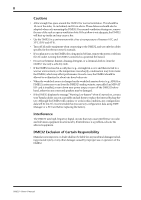 4
4 -
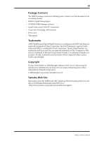 5
5 -
 6
6 -
 7
7 -
8
-
9
-
10
-
11
-
12
-
13
-
14
-
15
-
16
-
17
-
18
-
19
-
20
-
21
-
22
-
23
-
24
-
25
-
26
-
27
-
28
-
29
-
30
-
31
-
32
-
33
-
34
-
35
-
36
-
37
-
38
-
39
-
40
-
41
-
42
-
43
-
44
-
45
-
46
-
47
-
48
-
49
-
50
-
51
-
52
-
53
-
54
-
55
-
56
-
57
-
58
-
59
-
60
-
61
-
62
-
63
-
64
-
65
-
66
-
67
-
68
-
69
-
70
-
71
-
72
-
73
-
74
-
75
-
76
-
77
-
78
-
79
-
80
-
81
-
82
-
83
-
84
-
85
-
86
-
87
-
88
-
89
-
90
-
91
-
92
-
93
-
94
-
95
-
96
-
97
-
98
-
99
-
100
-
101
-
102
-
103
-
104
-
105
-
106
-
107
-
108
-
109
-
110
-
111
-
112
-
113
-
114
-
115
-
116
-
117
-
118
-
119
-
120
-
121
-
122
-
123
-
124
-
125
-
126
-
127
-
128
-
129
-
130
-
131
-
132
-
133
-
134
-
135
-
136
-
137
-
138
-
139
-
140
-
141
-
142
-
143
-
144
-
145
-
146
-
147
-
148
-
149
-
150
-
151
-
152
-
153
-
154
-
155
-
156
-
157
-
158
-
159
-
160
-
161
-
162
-
163
-
164
-
165
-
166
-
167
-
168
-
169
-
170
-
171
-
172
-
173
-
174
-
175
-
176
-
177
-
178
-
179
-
180
-
181
-
182
-
183
-
184
-
185
-
186
-
187
-
188
-
189
-
190
-
191
-
192
-
193
-
194
-
195
-
196
-
197
-
198
-
199
-
200
-
201
-
202
-
203
-
204
-
205
-
206
-
207
-
208
-
209
-
210
-
211
-
212
-
213
-
214
-
215
-
216
-
217
-
218
-
219
-
220
-
221
-
222
-
223
-
224
-
225
-
226
-
227
-
228
-
229
-
230
-
231
-
232
-
233
-
234
-
235
-
236
-
237
-
238
-
239
-
240
-
241
-
242
-
243
-
244
-
245
-
246
-
247
-
248
-
249
-
250
-
251
-
252
-
253
-
254
-
255
-
256
-
257
-
258
-
259
-
260
-
261
-
262
-
263
-
264
-
265
-
266
-
267
-
268
-
269
-
270
-
271
-
272
-
273
-
274
-
275
-
276
-
277
-
278
-
279
-
280
-
281
-
282
-
283
-
284
-
285
-
286
-
287
-
288
-
289
-
290
-
291
-
292
-
293
-
294
-
295
-
296
 |
 |
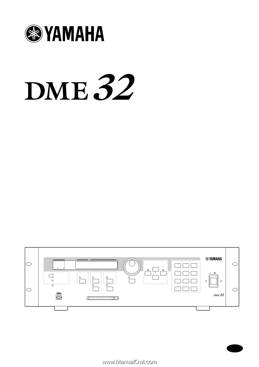
DIGITAL MIXING ENGINE
Owner’s Manual
E
Keep This Manual For Future Reference.
SCENE NO.
CONFIGURATION
48kHz
LOCK
EMERGENCY
44.1kHz
SCENE
COMPONENT
PARAMETER
UTILITY
VALUE
CARD
USER DEFINE
PROTECT
INC
DEC
DIGITAL MIXING ENGINE
POWER
ON
OFF
7
8
9
4
5
6
1
2
0
STORE
RECALL
3
SCENE
RECALL
DATA
X
Digital
X
Mixing
X
Engine
XXXXX
YAMAHA
X
DME32
88