Yamaha DME32 DME32 Owners Manual - Page 157
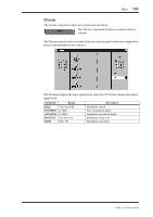
Flange, The Flange control window consists
 |
View all Yamaha DME32 manuals
Add to My Manuals
Save this manual to your list of manuals |
Page 157 highlights
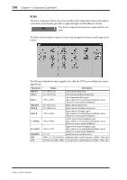
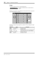
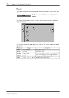
152 Chapter 9-Component Guide Part II Flange The Flange component offers two-channel flanging effects. The Flange component features two inputs and two outputs. The Flange control window consists of flanger controls, input level meters, output level meters, and modulation wave selector. The IN meters display the input signal levels, while the OUT meters display the output signal levels. Parameter Range Description FREQ. DEPTH 0.05-40.00 Hz 0-100% FB.GAIN -99 to +99% MOD.DLY 0.0-500.0 ms WAVE SINE, TRI Modulation speed Modulation depth Feedback gain (plus values for normal-phase feedback, minus values for reverse-phase feedback) Modulation delay time Modulation waveform DME32-Owner's Manual
-
 1
1 -
2
-
3
-
4
-
5
-
6
-
7
-
8
-
9
-
10
-
11
-
12
-
13
-
14
-
15
-
16
-
17
-
18
-
19
-
20
-
21
-
22
-
23
-
24
-
25
-
26
-
27
-
28
-
29
-
30
-
31
-
32
-
33
-
34
-
35
-
36
-
37
-
38
-
39
-
40
-
41
-
42
-
43
-
44
-
45
-
46
-
47
-
48
-
49
-
50
-
51
-
52
-
53
-
54
-
55
-
56
-
57
-
58
-
59
-
60
-
61
-
62
-
63
-
64
-
65
-
66
-
67
-
68
-
69
-
70
-
71
-
72
-
73
-
74
-
75
-
76
-
77
-
78
-
79
-
80
-
81
-
82
-
83
-
84
-
85
-
86
-
87
-
88
-
89
-
90
-
91
-
92
-
93
-
94
-
95
-
96
-
97
-
98
-
99
-
100
-
101
-
102
-
103
-
104
-
105
-
106
-
107
-
108
-
109
-
110
-
111
-
112
-
113
-
114
-
115
-
116
-
117
-
118
-
119
-
120
-
121
-
122
-
123
-
124
-
125
-
126
-
127
-
128
-
129
-
130
-
131
-
132
-
133
-
134
-
135
-
136
-
137
-
138
-
139
-
140
-
141
-
142
-
143
-
144
-
145
-
146
-
147
-
148
-
149
-
150
-
151
-
 152
152 -
 153
153 -
 154
154 -
 155
155 -
 156
156 -
 157
157 -
 158
158 -
 159
159 -
 160
160 -
 161
161 -
 162
162 -
163
-
164
-
165
-
166
-
167
-
168
-
169
-
170
-
171
-
172
-
173
-
174
-
175
-
176
-
177
-
178
-
179
-
180
-
181
-
182
-
183
-
184
-
185
-
186
-
187
-
188
-
189
-
190
-
191
-
192
-
193
-
194
-
195
-
196
-
197
-
198
-
199
-
200
-
201
-
202
-
203
-
204
-
205
-
206
-
207
-
208
-
209
-
210
-
211
-
212
-
213
-
214
-
215
-
216
-
217
-
218
-
219
-
220
-
221
-
222
-
223
-
224
-
225
-
226
-
227
-
228
-
229
-
230
-
231
-
232
-
233
-
234
-
235
-
236
-
237
-
238
-
239
-
240
-
241
-
242
-
243
-
244
-
245
-
246
-
247
-
248
-
249
-
250
-
251
-
252
-
253
-
254
-
255
-
256
-
257
-
258
-
259
-
260
-
261
-
262
-
263
-
264
-
265
-
266
-
267
-
268
-
269
-
270
-
271
-
272
-
273
-
274
-
275
-
276
-
277
-
278
-
279
-
280
-
281
-
282
-
283
-
284
-
285
-
286
-
287
-
288
-
289
-
290
-
291
-
292
-
293
-
294
-
295
-
296
 |
 |

152
Chapter 9
—
Component Guide Part II
DME32
—
Owner
’
s Manual
Flange
The Flange component offers two-channel
fl
anging effects.
The Flange component features two inputs and two
outputs.
The Flange control window consists of
fl
anger controls, input level meters, output level
meters, and modulation wave selector.
The IN meters display the input signal levels, while the OUT meters display the output
signal levels.
Parameter
Range
Description
FREQ.
0.05
–
40.00 Hz
Modulation speed
DEPTH
0
–
100%
Modulation depth
FB.GAIN
–
99 to +99%
Feedback gain (plus values for normal-phase feed-
back, minus values for reverse-phase feedback)
MOD.DLY
0.0
–
500.0 ms
Modulation delay time
WAVE
SINE, TRI
Modulation waveform