Yamaha DME32 DME32 Owners Manual - Page 221
Parameter Control, potentiometer to the IN, +V, and GND terminals, continuously
 |
View all Yamaha DME32 manuals
Add to My Manuals
Save this manual to your list of manuals |
Page 221 highlights
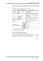
216 Chapter 11-GPI Interface Parameter Control The following table describes how buttons (ON/OFF parameters), rotary controls and sliders, and pop-up menus can be controlled using a normally open switch. GPI connection IN +V High = switch closed Low = switch open Terminal Usage Buttons (ON/OFF parameters) Normally Open Switch Rotary controls & sliders Pop-up menus Normal High = ON Low = OFF High = max. value Low = min. value High = top setting Low = bottom setting Reverse High = OFF Low = ON Low-to-high Toggles between ON and OFF when IN changes from low to high (i.e., when switch pressed) High-to-low Toggles between ON and OFF when IN changes from high to low (i.e., when switch released) High = min. value Low = max. value Toggles between min. and max. values when IN changes from low to high (i.e., when switch pressed) Toggles between min. and max. values when IN changes from high to low (i.e., when switch released) High = bottom setting Low = top setting Toggles between top and bottom settings when IN changes from low to high (i.e., when switch pressed) Toggles between top and bottom settings when IN changes from high to low (i.e., when switch released) The next table describes how buttons (ON/OFF parameters), rotary controls and sliders, and pop-up menus can be controlled using a 10k-ohm linear-scale potentiometer. By connecting the potentiometer to the IN, +V, and GND terminals, continuously variable parameter control is possible. GPI connection IN +V GND 10k ohm linear potentiometer High = potentiometer max. Low = potentiometer min. Terminal Usage Buttons1 (ON/OFF parameters) 10k-ohm linear potentiometer Rotary controls & sliders Pop-up menus Normal High = ON Low = OFF Reverse High = OFF Low = ON Low-to-high Toggles between ON and OFF when IN changes from low to high (i.e., when potentiometer raised) High-to-low Toggles between ON and OFF when IN changes from high to low (i.e., when potentiometer lowered) Continuously variable, High = max. value Low = min. value Continuously variable, High = min. value Low = max. value Toggles between min. and max. values when IN changes from low to high (i.e., when potentiometer raised) Toggles between min. and max. values when IN changes from high to low (i.e., when potentiometer lowered) Continuously variable, High = top setting Low = bottom setting Continuously variable, High = bottom setting Low = top setting Toggles between top and bottom settings when IN changes from low to high (i.e., when potentiometer raised) Toggles between top and bottom settings when IN changes from high to low (i.e., when potentiometer lowered) 1. Transition between low and high occurs at the center position. DME32-Owner's Manual
-
 1
1 -
2
-
3
-
4
-
5
-
6
-
7
-
8
-
9
-
10
-
11
-
12
-
13
-
14
-
15
-
16
-
17
-
18
-
19
-
20
-
21
-
22
-
23
-
24
-
25
-
26
-
27
-
28
-
29
-
30
-
31
-
32
-
33
-
34
-
35
-
36
-
37
-
38
-
39
-
40
-
41
-
42
-
43
-
44
-
45
-
46
-
47
-
48
-
49
-
50
-
51
-
52
-
53
-
54
-
55
-
56
-
57
-
58
-
59
-
60
-
61
-
62
-
63
-
64
-
65
-
66
-
67
-
68
-
69
-
70
-
71
-
72
-
73
-
74
-
75
-
76
-
77
-
78
-
79
-
80
-
81
-
82
-
83
-
84
-
85
-
86
-
87
-
88
-
89
-
90
-
91
-
92
-
93
-
94
-
95
-
96
-
97
-
98
-
99
-
100
-
101
-
102
-
103
-
104
-
105
-
106
-
107
-
108
-
109
-
110
-
111
-
112
-
113
-
114
-
115
-
116
-
117
-
118
-
119
-
120
-
121
-
122
-
123
-
124
-
125
-
126
-
127
-
128
-
129
-
130
-
131
-
132
-
133
-
134
-
135
-
136
-
137
-
138
-
139
-
140
-
141
-
142
-
143
-
144
-
145
-
146
-
147
-
148
-
149
-
150
-
151
-
152
-
153
-
154
-
155
-
156
-
157
-
158
-
159
-
160
-
161
-
162
-
163
-
164
-
165
-
166
-
167
-
168
-
169
-
170
-
171
-
172
-
173
-
174
-
175
-
176
-
177
-
178
-
179
-
180
-
181
-
182
-
183
-
184
-
185
-
186
-
187
-
188
-
189
-
190
-
191
-
192
-
193
-
194
-
195
-
196
-
197
-
198
-
199
-
200
-
201
-
202
-
203
-
204
-
205
-
206
-
207
-
208
-
209
-
210
-
211
-
212
-
213
-
214
-
215
-
 216
216 -
 217
217 -
 218
218 -
 219
219 -
 220
220 -
 221
221 -
 222
222 -
 223
223 -
 224
224 -
 225
225 -
 226
226 -
227
-
228
-
229
-
230
-
231
-
232
-
233
-
234
-
235
-
236
-
237
-
238
-
239
-
240
-
241
-
242
-
243
-
244
-
245
-
246
-
247
-
248
-
249
-
250
-
251
-
252
-
253
-
254
-
255
-
256
-
257
-
258
-
259
-
260
-
261
-
262
-
263
-
264
-
265
-
266
-
267
-
268
-
269
-
270
-
271
-
272
-
273
-
274
-
275
-
276
-
277
-
278
-
279
-
280
-
281
-
282
-
283
-
284
-
285
-
286
-
287
-
288
-
289
-
290
-
291
-
292
-
293
-
294
-
295
-
296
 |
 |
