Yamaha DME32 DME32 Owners Manual - Page 164
Mod Filter, Parameter, Range, Description, FREQ., DEPTH, OFFSET, RESO., PHASE, LEVEL
 |
View all Yamaha DME32 manuals
Add to My Manuals
Save this manual to your list of manuals |
Page 164 highlights
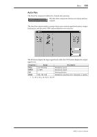
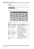
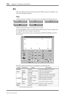
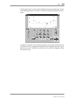
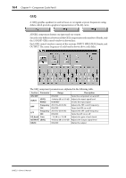
Effect 159 Mod Filter The Mod Filter component offers two-channel modulated filter effects. The Mod Filter component features two inputs and two outputs. The Mod Filter control window consists of mod filter controls, input level meters, output level meters, and a filter type selector. The IN meters display the input signal levels, while the OUT meters display the output signal levels. Parameter Range Description FREQ. DEPTH OFFSET RESO. PHASE LEVEL TYPE 0.05-40.00 Hz 0-100% 0-100 0-20 0.00-354.375° 0-100 LPF, HPF, BPF Modulation speed Modulation depth Filter frequency offset Filter resonance Left and right modulation phase difference Output level Filter type: low-pass, high-pass, or band-pass DME32-Owner's Manual
-
 1
1 -
2
-
3
-
4
-
5
-
6
-
7
-
8
-
9
-
10
-
11
-
12
-
13
-
14
-
15
-
16
-
17
-
18
-
19
-
20
-
21
-
22
-
23
-
24
-
25
-
26
-
27
-
28
-
29
-
30
-
31
-
32
-
33
-
34
-
35
-
36
-
37
-
38
-
39
-
40
-
41
-
42
-
43
-
44
-
45
-
46
-
47
-
48
-
49
-
50
-
51
-
52
-
53
-
54
-
55
-
56
-
57
-
58
-
59
-
60
-
61
-
62
-
63
-
64
-
65
-
66
-
67
-
68
-
69
-
70
-
71
-
72
-
73
-
74
-
75
-
76
-
77
-
78
-
79
-
80
-
81
-
82
-
83
-
84
-
85
-
86
-
87
-
88
-
89
-
90
-
91
-
92
-
93
-
94
-
95
-
96
-
97
-
98
-
99
-
100
-
101
-
102
-
103
-
104
-
105
-
106
-
107
-
108
-
109
-
110
-
111
-
112
-
113
-
114
-
115
-
116
-
117
-
118
-
119
-
120
-
121
-
122
-
123
-
124
-
125
-
126
-
127
-
128
-
129
-
130
-
131
-
132
-
133
-
134
-
135
-
136
-
137
-
138
-
139
-
140
-
141
-
142
-
143
-
144
-
145
-
146
-
147
-
148
-
149
-
150
-
151
-
152
-
153
-
154
-
155
-
156
-
157
-
158
-
 159
159 -
 160
160 -
 161
161 -
 162
162 -
 163
163 -
 164
164 -
 165
165 -
 166
166 -
 167
167 -
 168
168 -
 169
169 -
170
-
171
-
172
-
173
-
174
-
175
-
176
-
177
-
178
-
179
-
180
-
181
-
182
-
183
-
184
-
185
-
186
-
187
-
188
-
189
-
190
-
191
-
192
-
193
-
194
-
195
-
196
-
197
-
198
-
199
-
200
-
201
-
202
-
203
-
204
-
205
-
206
-
207
-
208
-
209
-
210
-
211
-
212
-
213
-
214
-
215
-
216
-
217
-
218
-
219
-
220
-
221
-
222
-
223
-
224
-
225
-
226
-
227
-
228
-
229
-
230
-
231
-
232
-
233
-
234
-
235
-
236
-
237
-
238
-
239
-
240
-
241
-
242
-
243
-
244
-
245
-
246
-
247
-
248
-
249
-
250
-
251
-
252
-
253
-
254
-
255
-
256
-
257
-
258
-
259
-
260
-
261
-
262
-
263
-
264
-
265
-
266
-
267
-
268
-
269
-
270
-
271
-
272
-
273
-
274
-
275
-
276
-
277
-
278
-
279
-
280
-
281
-
282
-
283
-
284
-
285
-
286
-
287
-
288
-
289
-
290
-
291
-
292
-
293
-
294
-
295
-
296
 |
 |

Effect
159
DME32
—
Owner
’
s Manual
Mod Filter
The Mod Filter component offers two-channel modulated
fi
lter effects.
The Mod Filter component features two inputs and two
outputs.
The Mod Filter control window consists of mod
fi
lter controls, input level meters, out-
put level meters, and a
fi
lter type selector.
The IN meters display the input signal levels, while the OUT meters display the output
signal levels.
Parameter
Range
Description
FREQ.
0.05
–
40.00 Hz
Modulation speed
DEPTH
0
–
100%
Modulation depth
OFFSET
0
–
100
Filter frequency offset
RESO.
0
–
20
Filter resonance
PHASE
0.00
–
354.375
°
Left and right modulation phase difference
LEVEL
0
–
100
Output level
TYPE
LPF, HPF, BPF
Filter type: low-pass, high-pass, or band-pass