Yamaha DME32 DME32 Owners Manual - Page 26
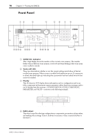
QCARD eject button RUTILITY button & indicator SVALUE button & indicator TUSER DEFINE button & indicator UCursor buttons VPOWER switch
 |
View all Yamaha DME32 manuals
Add to My Manuals
Save this manual to your list of manuals |
Page 26 highlights
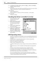
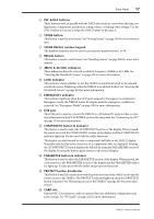
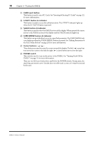
18 Chapter 3-Touring the DME32 Q CARD eject button This button is used to eject PC Cards. See "Inserting & Ejecting PC Cards" on page 222 for more information. R UTILITY button & indicator This button is used to access the utility functions. The UTILITY indicator lights up when the [UTILITY] button is pressed. S VALUE button & indicator This button is used to select the VALUE section of the display. When pressed, the cursor moves to the VALUE section of the display and the VALUE indicator lights up. T USER DEFINE button & indicator This button can provide direct access to a specified parameter. The USER DEFINE indicator lights up when the [USER DEFINE] button is pressed. See "Editing Parameters & the User Define Button" on page 201 for more information. U Cursor buttons ( / ) These buttons are used to move the cursor around the display. The left ( ) cursor button moves the cursor to the left; the right ( ) cursor button moves it to the right. V POWER switch This switch is used to turn on the power to the DME32. See "Turning On & Off the DME32" on page 11 for more information. There are two M3 screw holes above and below the POWER switch, 34 mm apart, for attaching a protective cover. Yamaha does not offer such a cover, so it must be sourced by the user. DME32-Owner's Manual
-
 1
1 -
2
-
3
-
4
-
5
-
6
-
7
-
8
-
9
-
10
-
11
-
12
-
13
-
14
-
15
-
16
-
17
-
18
-
19
-
20
-
 21
21 -
 22
22 -
 23
23 -
 24
24 -
 25
25 -
 26
26 -
 27
27 -
 28
28 -
 29
29 -
 30
30 -
 31
31 -
32
-
33
-
34
-
35
-
36
-
37
-
38
-
39
-
40
-
41
-
42
-
43
-
44
-
45
-
46
-
47
-
48
-
49
-
50
-
51
-
52
-
53
-
54
-
55
-
56
-
57
-
58
-
59
-
60
-
61
-
62
-
63
-
64
-
65
-
66
-
67
-
68
-
69
-
70
-
71
-
72
-
73
-
74
-
75
-
76
-
77
-
78
-
79
-
80
-
81
-
82
-
83
-
84
-
85
-
86
-
87
-
88
-
89
-
90
-
91
-
92
-
93
-
94
-
95
-
96
-
97
-
98
-
99
-
100
-
101
-
102
-
103
-
104
-
105
-
106
-
107
-
108
-
109
-
110
-
111
-
112
-
113
-
114
-
115
-
116
-
117
-
118
-
119
-
120
-
121
-
122
-
123
-
124
-
125
-
126
-
127
-
128
-
129
-
130
-
131
-
132
-
133
-
134
-
135
-
136
-
137
-
138
-
139
-
140
-
141
-
142
-
143
-
144
-
145
-
146
-
147
-
148
-
149
-
150
-
151
-
152
-
153
-
154
-
155
-
156
-
157
-
158
-
159
-
160
-
161
-
162
-
163
-
164
-
165
-
166
-
167
-
168
-
169
-
170
-
171
-
172
-
173
-
174
-
175
-
176
-
177
-
178
-
179
-
180
-
181
-
182
-
183
-
184
-
185
-
186
-
187
-
188
-
189
-
190
-
191
-
192
-
193
-
194
-
195
-
196
-
197
-
198
-
199
-
200
-
201
-
202
-
203
-
204
-
205
-
206
-
207
-
208
-
209
-
210
-
211
-
212
-
213
-
214
-
215
-
216
-
217
-
218
-
219
-
220
-
221
-
222
-
223
-
224
-
225
-
226
-
227
-
228
-
229
-
230
-
231
-
232
-
233
-
234
-
235
-
236
-
237
-
238
-
239
-
240
-
241
-
242
-
243
-
244
-
245
-
246
-
247
-
248
-
249
-
250
-
251
-
252
-
253
-
254
-
255
-
256
-
257
-
258
-
259
-
260
-
261
-
262
-
263
-
264
-
265
-
266
-
267
-
268
-
269
-
270
-
271
-
272
-
273
-
274
-
275
-
276
-
277
-
278
-
279
-
280
-
281
-
282
-
283
-
284
-
285
-
286
-
287
-
288
-
289
-
290
-
291
-
292
-
293
-
294
-
295
-
296
 |
 |
