Yamaha DME32 DME32 Owners Manual - Page 25
Yamaha DME32 Manual
 |
View all Yamaha DME32 manuals
Add to My Manuals
Save this manual to your list of manuals |
Page 25 highlights
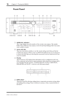
Front Panel 17 E INC & DEC buttons These buttons work in parallel with the DATA wheel and are used when selecting configurations, components, parameters, setting values, or making other settings. Use the [INC] button to increase a value; the [DEC] button to decrease it. F STORE button This button is used to store scenes. See "Storing Scenes" on page 199 for more information. G SCENE RECALL number keypad The number keypad is used to enter scene memory numbers from 1 to 99. H RECALL button This button is used to recall scenes. See "Recalling Scenes" on page 200 for more information. I 48kHz & 44.1kHz indicators These indicators show the selected wordclock frequency: 48 kHz or 44.1 kHz. See "Selecting the Wordclock Source" on page 229 for more information. J LOCK indicator This indicator shows whether or not the DME32 is wordclock locked to the selected wordclock source. It lights up when the DME32 is wordclock locked. See "Selecting the Wordclock Source" on page 229 for more information. K EMERGENCY indicator This indicator lights up when the GPI input assigned to Emergency is activated. In Emergency mode, the DME32 mutes all outputs until the emergency condition is removed. See "Emergency Mode" on page 220 for more information. L USB port This USB port is used to connect the DME32 to a Windows PC and provides a convenient alternative to the PC CONTROL port on the rear panel. See "Connecting to a PC" on page 10 for more information. M COMPONENT button & indicator This button is used to select the COMPONENT section of the display. When pressed, the cursor moves to the COMPONENT section of the display and the COMPONENT indicator lights up. It's also used with the utility functions. This button can also be used to view a component's full title on the DME32 display. Normally only the first seven characters of a component's title are displayed. Pressing the [COMPONENT] button displays the full title by using the PARAMETER section of the display. Pressing the button again returns to the normal display. N PARAMETER button & indicator This button is used to select the PARAMETER section of the display. When pressed, the cursor moves to the PARAMETER section of the display and the PARAMETER indicator lights up. It's also used with the utility and protection functions. O PROTECT button & indicator This button is used in conjunction with the protection functions, which can be used to restrict access to the DME32. The PROTECT indicator lights up when the [PROTECT] button is pressed. See "Restricting Access to the DME32" on page 203 for more information. P CARD slot Optional PC Card memory cards are inserted here for additional configuration and scene storage. See "PC Cards" on page 221 for more information. DME32-Owner's Manual
-
 1
1 -
2
-
3
-
4
-
5
-
6
-
7
-
8
-
9
-
10
-
11
-
12
-
13
-
14
-
15
-
16
-
17
-
18
-
19
-
 20
20 -
 21
21 -
 22
22 -
 23
23 -
 24
24 -
 25
25 -
 26
26 -
 27
27 -
 28
28 -
 29
29 -
 30
30 -
31
-
32
-
33
-
34
-
35
-
36
-
37
-
38
-
39
-
40
-
41
-
42
-
43
-
44
-
45
-
46
-
47
-
48
-
49
-
50
-
51
-
52
-
53
-
54
-
55
-
56
-
57
-
58
-
59
-
60
-
61
-
62
-
63
-
64
-
65
-
66
-
67
-
68
-
69
-
70
-
71
-
72
-
73
-
74
-
75
-
76
-
77
-
78
-
79
-
80
-
81
-
82
-
83
-
84
-
85
-
86
-
87
-
88
-
89
-
90
-
91
-
92
-
93
-
94
-
95
-
96
-
97
-
98
-
99
-
100
-
101
-
102
-
103
-
104
-
105
-
106
-
107
-
108
-
109
-
110
-
111
-
112
-
113
-
114
-
115
-
116
-
117
-
118
-
119
-
120
-
121
-
122
-
123
-
124
-
125
-
126
-
127
-
128
-
129
-
130
-
131
-
132
-
133
-
134
-
135
-
136
-
137
-
138
-
139
-
140
-
141
-
142
-
143
-
144
-
145
-
146
-
147
-
148
-
149
-
150
-
151
-
152
-
153
-
154
-
155
-
156
-
157
-
158
-
159
-
160
-
161
-
162
-
163
-
164
-
165
-
166
-
167
-
168
-
169
-
170
-
171
-
172
-
173
-
174
-
175
-
176
-
177
-
178
-
179
-
180
-
181
-
182
-
183
-
184
-
185
-
186
-
187
-
188
-
189
-
190
-
191
-
192
-
193
-
194
-
195
-
196
-
197
-
198
-
199
-
200
-
201
-
202
-
203
-
204
-
205
-
206
-
207
-
208
-
209
-
210
-
211
-
212
-
213
-
214
-
215
-
216
-
217
-
218
-
219
-
220
-
221
-
222
-
223
-
224
-
225
-
226
-
227
-
228
-
229
-
230
-
231
-
232
-
233
-
234
-
235
-
236
-
237
-
238
-
239
-
240
-
241
-
242
-
243
-
244
-
245
-
246
-
247
-
248
-
249
-
250
-
251
-
252
-
253
-
254
-
255
-
256
-
257
-
258
-
259
-
260
-
261
-
262
-
263
-
264
-
265
-
266
-
267
-
268
-
269
-
270
-
271
-
272
-
273
-
274
-
275
-
276
-
277
-
278
-
279
-
280
-
281
-
282
-
283
-
284
-
285
-
286
-
287
-
288
-
289
-
290
-
291
-
292
-
293
-
294
-
295
-
296
 |
 |
