Yamaha DME32 DME32 Owners Manual - Page 163
Dual Pitch, Parameter, Range, Description, PITCH 1, FINE 1, PAN 1, DELAY 1, FB.G 1, LEVEL 1
 |
View all Yamaha DME32 manuals
Add to My Manuals
Save this manual to your list of manuals |
Page 163 highlights
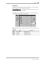
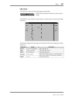
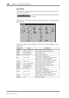
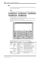
158 Chapter 9-Component Guide Part II Dual Pitch The Dual Pitch component offers two-channel pitch shifting with independent pitch controls for each channel. The Dual Pitch component features two inputs and two outputs. The Dual Pitch control window consists of pitch controls, input level meters, and output level meters. The IN meters display the input signal levels, while the OUT meters display the output signal levels. Parameter Range Description PITCH 1 FINE 1 PAN 1 DELAY 1 FB.G 1 LEVEL 1 PITCH 2 FINE 2 PAN 2 DELAY 2 FB.G 2 LEVEL 2 MODE -24 to +24 semitones -50 to +50 cents L16-CENTER-R16 0.0-1000.0 ms -99 to +99% -100 to +100 -24 to +24 semitones -50 to +50 cents L16-CENTER-R16 0.0-1000.0 ms -99 to +99% -100 to +100 1-10 Pitch change 1 pitch shift amount Pitch change 1 pitch shift fine amount Pitch change 1 pan Pitch change 1 delay time Pitch change 1 feedback gain (plus values for normal-phase feedback, minus values for reverse-phase feedback) Pitch change 1 level (plus values for normal phase, minus values for reverse phase) Pitch change 2 pitch shift amount Pitch change 2 pitch shift fine amount Pitch change 2 pan Pitch change 2 delay time Pitch change 2 feedback gain (plus values for normal-phase feedback, minus values for reverse-phase feedback) Pitch change 2 level (plus values for normal phase, minus values for reverse phase) Pitch shift precision DME32-Owner's Manual
-
 1
1 -
2
-
3
-
4
-
5
-
6
-
7
-
8
-
9
-
10
-
11
-
12
-
13
-
14
-
15
-
16
-
17
-
18
-
19
-
20
-
21
-
22
-
23
-
24
-
25
-
26
-
27
-
28
-
29
-
30
-
31
-
32
-
33
-
34
-
35
-
36
-
37
-
38
-
39
-
40
-
41
-
42
-
43
-
44
-
45
-
46
-
47
-
48
-
49
-
50
-
51
-
52
-
53
-
54
-
55
-
56
-
57
-
58
-
59
-
60
-
61
-
62
-
63
-
64
-
65
-
66
-
67
-
68
-
69
-
70
-
71
-
72
-
73
-
74
-
75
-
76
-
77
-
78
-
79
-
80
-
81
-
82
-
83
-
84
-
85
-
86
-
87
-
88
-
89
-
90
-
91
-
92
-
93
-
94
-
95
-
96
-
97
-
98
-
99
-
100
-
101
-
102
-
103
-
104
-
105
-
106
-
107
-
108
-
109
-
110
-
111
-
112
-
113
-
114
-
115
-
116
-
117
-
118
-
119
-
120
-
121
-
122
-
123
-
124
-
125
-
126
-
127
-
128
-
129
-
130
-
131
-
132
-
133
-
134
-
135
-
136
-
137
-
138
-
139
-
140
-
141
-
142
-
143
-
144
-
145
-
146
-
147
-
148
-
149
-
150
-
151
-
152
-
153
-
154
-
155
-
156
-
157
-
 158
158 -
 159
159 -
 160
160 -
 161
161 -
 162
162 -
 163
163 -
 164
164 -
 165
165 -
 166
166 -
 167
167 -
 168
168 -
169
-
170
-
171
-
172
-
173
-
174
-
175
-
176
-
177
-
178
-
179
-
180
-
181
-
182
-
183
-
184
-
185
-
186
-
187
-
188
-
189
-
190
-
191
-
192
-
193
-
194
-
195
-
196
-
197
-
198
-
199
-
200
-
201
-
202
-
203
-
204
-
205
-
206
-
207
-
208
-
209
-
210
-
211
-
212
-
213
-
214
-
215
-
216
-
217
-
218
-
219
-
220
-
221
-
222
-
223
-
224
-
225
-
226
-
227
-
228
-
229
-
230
-
231
-
232
-
233
-
234
-
235
-
236
-
237
-
238
-
239
-
240
-
241
-
242
-
243
-
244
-
245
-
246
-
247
-
248
-
249
-
250
-
251
-
252
-
253
-
254
-
255
-
256
-
257
-
258
-
259
-
260
-
261
-
262
-
263
-
264
-
265
-
266
-
267
-
268
-
269
-
270
-
271
-
272
-
273
-
274
-
275
-
276
-
277
-
278
-
279
-
280
-
281
-
282
-
283
-
284
-
285
-
286
-
287
-
288
-
289
-
290
-
291
-
292
-
293
-
294
-
295
-
296
 |
 |
