Yamaha DME32 DME32 Owners Manual - Page 150
Gate Reverb & Reverse Gate
 |
View all Yamaha DME32 manuals
Add to My Manuals
Save this manual to your list of manuals |
Page 150 highlights
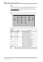
Effect 145 Gate Reverb & Reverse Gate The Gate Reverb component offers an early-reflection reverb with gate, while the Reverse Gate component offers early-reflections with a reverse gate. Both components feature one input and stereo outputs. Since the only difference between these components is their reverb algorithm, only the Gate Reverb control window is shown here. Each control window consists of early reflection controls, input level meter, stereo output level meters, and reflection pattern type selector. The IN meter displays the input signal level, while the OUT meters display the stereo output signal levels. Parameter Range Description ROOMSIZE LIVENESS INI.DLY DIFF. DENSITY ER NUM. HI.RATIO FB. GAIN HPF LPF TYPE 0.1-20.0 0-10 0.0-500.0 ms 0-10 0-100% 1-19 0.1-1.0 -99 to +99% THRU, 21.2 Hz-8.00 kHz 50.0 Hz-16.0 kHz, THRU Type-A, Type-B Reflection spacing Early reflections decay characteristics (0 = dead, 10 = live) Initial delay before reverb begins Reverb diffusion (left-right reverb spread) Reverb density Number of early reflections High-frequency feedback ratio Feedback gain High-pass filter cutoff frequency (THRU = filter off) Low-pass filter cutoff frequency (THRU = filter off) Type of early reflection simulation DME32-Owner's Manual
-
 1
1 -
2
-
3
-
4
-
5
-
6
-
7
-
8
-
9
-
10
-
11
-
12
-
13
-
14
-
15
-
16
-
17
-
18
-
19
-
20
-
21
-
22
-
23
-
24
-
25
-
26
-
27
-
28
-
29
-
30
-
31
-
32
-
33
-
34
-
35
-
36
-
37
-
38
-
39
-
40
-
41
-
42
-
43
-
44
-
45
-
46
-
47
-
48
-
49
-
50
-
51
-
52
-
53
-
54
-
55
-
56
-
57
-
58
-
59
-
60
-
61
-
62
-
63
-
64
-
65
-
66
-
67
-
68
-
69
-
70
-
71
-
72
-
73
-
74
-
75
-
76
-
77
-
78
-
79
-
80
-
81
-
82
-
83
-
84
-
85
-
86
-
87
-
88
-
89
-
90
-
91
-
92
-
93
-
94
-
95
-
96
-
97
-
98
-
99
-
100
-
101
-
102
-
103
-
104
-
105
-
106
-
107
-
108
-
109
-
110
-
111
-
112
-
113
-
114
-
115
-
116
-
117
-
118
-
119
-
120
-
121
-
122
-
123
-
124
-
125
-
126
-
127
-
128
-
129
-
130
-
131
-
132
-
133
-
134
-
135
-
136
-
137
-
138
-
139
-
140
-
141
-
142
-
143
-
144
-
 145
145 -
 146
146 -
 147
147 -
 148
148 -
 149
149 -
 150
150 -
 151
151 -
 152
152 -
 153
153 -
 154
154 -
 155
155 -
156
-
157
-
158
-
159
-
160
-
161
-
162
-
163
-
164
-
165
-
166
-
167
-
168
-
169
-
170
-
171
-
172
-
173
-
174
-
175
-
176
-
177
-
178
-
179
-
180
-
181
-
182
-
183
-
184
-
185
-
186
-
187
-
188
-
189
-
190
-
191
-
192
-
193
-
194
-
195
-
196
-
197
-
198
-
199
-
200
-
201
-
202
-
203
-
204
-
205
-
206
-
207
-
208
-
209
-
210
-
211
-
212
-
213
-
214
-
215
-
216
-
217
-
218
-
219
-
220
-
221
-
222
-
223
-
224
-
225
-
226
-
227
-
228
-
229
-
230
-
231
-
232
-
233
-
234
-
235
-
236
-
237
-
238
-
239
-
240
-
241
-
242
-
243
-
244
-
245
-
246
-
247
-
248
-
249
-
250
-
251
-
252
-
253
-
254
-
255
-
256
-
257
-
258
-
259
-
260
-
261
-
262
-
263
-
264
-
265
-
266
-
267
-
268
-
269
-
270
-
271
-
272
-
273
-
274
-
275
-
276
-
277
-
278
-
279
-
280
-
281
-
282
-
283
-
284
-
285
-
286
-
287
-
288
-
289
-
290
-
291
-
292
-
293
-
294
-
295
-
296
 |
 |
