3Com 8760 User Guide - Page 18
Before You Begin, between 0° C to 50° C 14° F to 122° F. - ap
 |
UPC - 662705506531
View all 3Com 8760 manuals
Add to My Manuals
Save this manual to your list of manuals |
Page 18 highlights
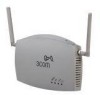
CHAPTER 2: INSTALLING THE ACCESS POINT Configuring a wireless LAN can be as easy as placing a 3Com Wireless Access Point in a central area and making the necessary connections to the AP and the clients. However, installing multiple Access Points may require more planning. If you plan to use an optional antenna instead of the standard detachable antennas that are supplied, review "Selecting and Connecting a Different Antenna Model" on page 2-12 before selecting the final location and be sure to allow for routing the antenna cable as required. For optimal performance, ensure the access point operates in temperature ranges between 0° C to 50° C (14° F to 122° F). ! CAUTION: Regulatory restrictions dictate that when this device is operational, the minimal body-to-antenna distance is 20 cm (8 inches). BEFORE YOU BEGIN Record the access point MAC address in a safe place before the access point is installed in a hard-to-reach location. The MAC address is printed on the back of the access point housing. The following illustration shows the front and rear views of the access point, including the LEDs and connecting ports. 2-4
-
 1
1 -
2
-
3
-
4
-
5
-
6
-
7
-
8
-
9
-
10
-
11
-
12
-
 13
13 -
 14
14 -
 15
15 -
 16
16 -
 17
17 -
 18
18 -
 19
19 -
 20
20 -
 21
21 -
 22
22 -
 23
23 -
24
-
25
-
26
-
27
-
28
-
29
-
30
-
31
-
32
-
33
-
34
-
35
-
36
-
37
-
38
-
39
-
40
-
41
-
42
-
43
-
44
-
45
-
46
-
47
-
48
-
49
-
50
-
51
-
52
-
53
-
54
-
55
-
56
-
57
-
58
-
59
-
60
-
61
-
62
-
63
-
64
-
65
-
66
-
67
-
68
-
69
-
70
-
71
-
72
-
73
-
74
-
75
-
76
-
77
-
78
-
79
-
80
-
81
-
82
-
83
-
84
-
85
-
86
-
87
-
88
-
89
-
90
-
91
-
92
-
93
-
94
-
95
-
96
-
97
-
98
-
99
-
100
-
101
-
102
-
103
-
104
-
105
-
106
-
107
-
108
-
109
-
110
-
111
-
112
-
113
-
114
-
115
-
116
-
117
-
118
-
119
-
120
-
121
-
122
-
123
-
124
-
125
-
126
-
127
-
128
-
129
-
130
-
131
-
132
-
133
-
134
-
135
-
136
-
137
-
138
-
139
-
140
-
141
-
142
-
143
-
144
-
145
-
146
-
147
-
148
-
149
-
150
-
151
-
152
-
153
-
154
-
155
-
156
-
157
-
158
-
159
-
160
-
161
-
162
-
163
-
164
-
165
-
166
-
167
-
168
-
169
-
170
-
171
-
172
-
173
-
174
-
175
-
176
-
177
-
178
-
179
-
180
-
181
-
182
-
183
-
184
-
185
-
186
-
187
-
188
-
189
-
190
-
191
-
192
-
193
-
194
-
195
-
196
-
197
-
198
-
199
-
200
-
201
-
202
-
203
-
204
-
205
-
206
-
207
-
208
-
209
-
210
-
211
-
212
-
213
-
214
-
215
-
216
-
217
-
218
-
219
-
220
-
221
-
222
-
223
-
224
-
225
-
226
-
227
-
228
-
229
-
230
-
231
-
232
-
233
-
234
-
235
-
236
-
237
-
238
-
239
-
240
-
241
-
242
-
243
-
244
-
245
-
246
-
247
-
248
-
249
-
250
-
251
-
252
-
253
-
254
-
255
-
256
-
257
-
258
-
259
-
260
-
261
 |
 |
