D-Link DSN-540 Software User's Guide for DSN-1100-10 - Page 117
Working with Network Portals, Creating Network Portals
 |
UPC - 790069324017
View all D-Link DSN-540 manuals
Add to My Manuals
Save this manual to your list of manuals |
Page 117 highlights
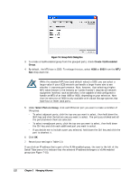
7.4 Working with Network Portals The iSCSI standard uses the concept of a network entity that represents a device or gateway attached to an IP network. In general, this network entity (either target or initiator) must contain one or more network portals that provide the physical connection to the IP network. An iSCSI node within a network entity can use any of the network portals to access the IP network. The iSCSI node is identified by its IP address within a network entity. It is possible to specify more than one network portal to a physical data port, but the IP addresses must be on different subnets. 7.4.1 Creating Network Portals The following procedure describes how to create network portals. When you create a network portal, you specify the IP address for each xStack Storage data port that will be communicating with your iSCSI initiator. Therefore, you must know which IP address(es) will be assigned to which the xStack Storage data port(s) before performing this procedure. As you create network portals, record your settings in Table C-4. Your iSCSI initiator must be aware of the IP address(es) you specify in this procedure so it can communicate with the target xStack Storage. When you create a network portal, you have the option of VLAN-enabling the ports. If you VLAN enable ports, the ports are deleted and then replaced by VLAN ports. As a result, any IP addresses associated with the ports are removed when they become VLAN enabled. The converse is true as well: when VLAN-enabled ports are replaced by ports that are not VLAN enabled. 1. In the Network Settings View, click an Ethernet port in the Main Display. 2. Perform one of the following steps: - On the Network menu, click Create Portal. - In the System Actions panel, click Create Portal. - Press the right mouse button and click Create Portal from the shortcut menu. Any of these steps displays the Create Portal dialog box (see Figure 7-5). xStack Storage Management Center Software User's Guide 107
-
 1
1 -
2
-
3
-
4
-
5
-
6
-
7
-
8
-
9
-
10
-
11
-
12
-
13
-
14
-
15
-
16
-
17
-
18
-
19
-
20
-
21
-
22
-
23
-
24
-
25
-
26
-
27
-
28
-
29
-
30
-
31
-
32
-
33
-
34
-
35
-
36
-
37
-
38
-
39
-
40
-
41
-
42
-
43
-
44
-
45
-
46
-
47
-
48
-
49
-
50
-
51
-
52
-
53
-
54
-
55
-
56
-
57
-
58
-
59
-
60
-
61
-
62
-
63
-
64
-
65
-
66
-
67
-
68
-
69
-
70
-
71
-
72
-
73
-
74
-
75
-
76
-
77
-
78
-
79
-
80
-
81
-
82
-
83
-
84
-
85
-
86
-
87
-
88
-
89
-
90
-
91
-
92
-
93
-
94
-
95
-
96
-
97
-
98
-
99
-
100
-
101
-
102
-
103
-
104
-
105
-
106
-
107
-
108
-
109
-
110
-
111
-
 112
112 -
 113
113 -
 114
114 -
 115
115 -
 116
116 -
 117
117 -
 118
118 -
 119
119 -
 120
120 -
 121
121 -
 122
122 -
123
-
124
-
125
-
126
-
127
-
128
-
129
-
130
-
131
-
132
-
133
-
134
-
135
-
136
-
137
-
138
-
139
-
140
-
141
-
142
-
143
-
144
-
145
-
146
-
147
-
148
-
149
-
150
-
151
-
152
-
153
-
154
-
155
-
156
-
157
-
158
 |
 |
