D-Link DSN-540 Software User's Guide for DSN-1100-10 - Page 18
VLANs, iSCSI Target Nodes, iSCSI Log-In, Sessions and Connections, Multiple Connections per Session
 |
UPC - 790069324017
View all D-Link DSN-540 manuals
Add to My Manuals
Save this manual to your list of manuals |
Page 18 highlights
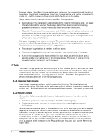
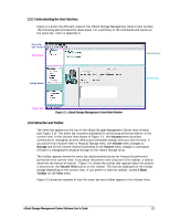
1.7 VLANs The xStack Storage system can use a Virtual LAN (VLAN) as a filter to identify the incoming packets it is to use on each LAG port. For each LAG port on which VLAN is to be enabled, a VLAN ID must be defined. On a VLAN-enabled LAG port, only packets with the given VLAN ID will be processed and all outgoing packets will be tagged with that VLAN ID. 1.8 LAGs The xStack Storage system manages the physical data ports on the enclosure's back panel using the concept of LAG ports. In a simple configuration, a LAG port associates a single Ethernet port (i.e., a physical data port) with a network portal (that defines an IP address). In this case, which is the default, there are no LAG ports shown on the Management Console and no management is necessary. Some server Operating Systems can aggregate multiple Ethernet ports into a LAG port and provide increased bandwidth. For example, aggregating two GbE ports could, theoretically, provide up to 2 Gb/s of throughput. Should a customer wish to utilize this feature, the Management Console can be used to replace the standard one-to-one relationship of Ethernet port to Network Portal with a LAG. LACP protocols are not supported. Static LAG configurations are the only supported option. 1.9 iSCSI Target Nodes An iSCSI target node is the method of providing a permissible access to storage on an xStack Storage system. One target node is automatically generated for each volume. The target node name includes the volume name with any spaces and other special characters removed. Access to that volume is granted to an initiator via its iSCSI Initiator Node name. Optionally, a CHAP secret can be specified for a volume for additional security authentication. 1.10 iSCSI Log-In, Sessions and Connections When an iSCSI initiator node needs access to the volumes in an xStack Storage system, it must log in to the target node associated with that volume. When the log in is accepted, an iSCSI session and an iSCSI connection is established. An initiator can log in to the same target node a second time, creating a second iSCSI connection within the original iSCSI session. 1.11 Multiple Connections per Session An initiator can log into a target more than once to establish multiple connections for a single session. Multiple connections can be used to increase bandwidth and provide redundancy. 8 Chapter 1 Introduction
-
 1
1 -
2
-
3
-
4
-
5
-
6
-
7
-
8
-
9
-
10
-
11
-
12
-
 13
13 -
 14
14 -
 15
15 -
 16
16 -
 17
17 -
 18
18 -
 19
19 -
 20
20 -
 21
21 -
 22
22 -
 23
23 -
24
-
25
-
26
-
27
-
28
-
29
-
30
-
31
-
32
-
33
-
34
-
35
-
36
-
37
-
38
-
39
-
40
-
41
-
42
-
43
-
44
-
45
-
46
-
47
-
48
-
49
-
50
-
51
-
52
-
53
-
54
-
55
-
56
-
57
-
58
-
59
-
60
-
61
-
62
-
63
-
64
-
65
-
66
-
67
-
68
-
69
-
70
-
71
-
72
-
73
-
74
-
75
-
76
-
77
-
78
-
79
-
80
-
81
-
82
-
83
-
84
-
85
-
86
-
87
-
88
-
89
-
90
-
91
-
92
-
93
-
94
-
95
-
96
-
97
-
98
-
99
-
100
-
101
-
102
-
103
-
104
-
105
-
106
-
107
-
108
-
109
-
110
-
111
-
112
-
113
-
114
-
115
-
116
-
117
-
118
-
119
-
120
-
121
-
122
-
123
-
124
-
125
-
126
-
127
-
128
-
129
-
130
-
131
-
132
-
133
-
134
-
135
-
136
-
137
-
138
-
139
-
140
-
141
-
142
-
143
-
144
-
145
-
146
-
147
-
148
-
149
-
150
-
151
-
152
-
153
-
154
-
155
-
156
-
157
-
158
 |
 |