Epson C7500G Technical Reference Guide - Page 152
Setting the Dip Switches, Setting Procedure
 |
View all Epson C7500G manuals
Add to My Manuals
Save this manual to your list of manuals |
Page 152 highlights
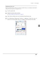
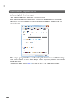
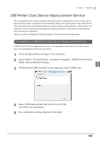
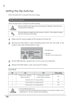
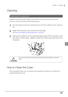
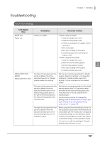
Setting the Dip Switches Follow the steps below to change the Dip switch settings. Setting Procedure Follow the steps below to change the Dip switch settings. CAUTION Before you remove the DIP switch cover, turn the product off. Otherwise, a short-circuit may cause the product to malfunction. DIP switch settings are enabled only when the power is turned on. If the settings are changed after that, the functions will not change. 1 Make sure the power supply for the product is turned off. 2 Remove the Dip switch cover mounting screw from the rear side of the product and open the Dip switch cover. Dip Switch Cover Dip Switch Dip Switch Cover mounting screw 3 Set the DIP switches, using the tip of a tool, such as a tweezers. 4 Replace the DIP switch cover, and screw it in place. Functions SW 1 2 3 4 ON OFF Power button: Disabled (Reset operation) Power button: Enabled (Power ON/OFF operation) Forbidden (Do not change setting) Reserved (Do not change setting) Reserved (Do not change setting) Initial setting OFF OFF OFF OFF CAUTION Do not change Dip switch 2 to 4. An SDHC memory card is located below the dip switches. Do not remove it, replace it or do anything else to it. This card is used for internal processing. 152
-
 1
1 -
2
-
3
-
4
-
5
-
6
-
7
-
8
-
9
-
10
-
11
-
12
-
13
-
14
-
15
-
16
-
17
-
18
-
19
-
20
-
21
-
22
-
23
-
24
-
25
-
26
-
27
-
28
-
29
-
30
-
31
-
32
-
33
-
34
-
35
-
36
-
37
-
38
-
39
-
40
-
41
-
42
-
43
-
44
-
45
-
46
-
47
-
48
-
49
-
50
-
51
-
52
-
53
-
54
-
55
-
56
-
57
-
58
-
59
-
60
-
61
-
62
-
63
-
64
-
65
-
66
-
67
-
68
-
69
-
70
-
71
-
72
-
73
-
74
-
75
-
76
-
77
-
78
-
79
-
80
-
81
-
82
-
83
-
84
-
85
-
86
-
87
-
88
-
89
-
90
-
91
-
92
-
93
-
94
-
95
-
96
-
97
-
98
-
99
-
100
-
101
-
102
-
103
-
104
-
105
-
106
-
107
-
108
-
109
-
110
-
111
-
112
-
113
-
114
-
115
-
116
-
117
-
118
-
119
-
120
-
121
-
122
-
123
-
124
-
125
-
126
-
127
-
128
-
129
-
130
-
131
-
132
-
133
-
134
-
135
-
136
-
137
-
138
-
139
-
140
-
141
-
142
-
143
-
144
-
145
-
146
-
 147
147 -
 148
148 -
 149
149 -
 150
150 -
 151
151 -
 152
152 -
 153
153 -
 154
154 -
 155
155 -
 156
156 -
 157
157 -
158
-
159
-
160
-
161
-
162
-
163
-
164
-
165
-
166
-
167
-
168
-
169
-
170
-
171
-
172
-
173
-
174
-
175
-
176
-
177
-
178
-
179
-
180
-
181
-
182
-
183
-
184
-
185
-
186
-
187
-
188
-
189
-
190
-
191
-
192
-
193
-
194
-
195
-
196
-
197
-
198
-
199
-
200
-
201
-
202
-
203
-
204
-
205
-
206
-
207
-
208
-
209
-
210
-
211
-
212
-
213
-
214
-
215
-
216
-
217
-
218
-
219
-
220
-
221
-
222
-
223
-
224
 |
 |