Epson C7500G Technical Reference Guide - Page 203
Die-cut labelBlack mark / Fanfold paper
 |
View all Epson C7500G manuals
Add to My Manuals
Save this manual to your list of manuals |
Page 203 highlights
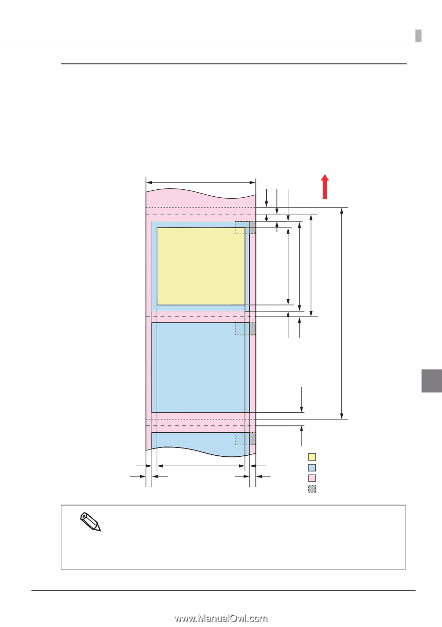
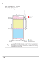
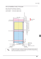
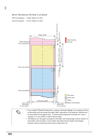
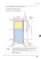
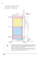
Die-cut label(Black mark) / Fanfold paper When "Borderless Printing" is disabled Vertical margins: 1.5 mm {0.06"} (Typical value) Lateral margins: 1.5 mm {0.06"} (Typical value) Perforated line Auto-cut position Paper width 0.5 to 1 mm { 0.02 to 0.04"} 1.5 to 3.0 mm {0.06 to 0.12" } 1.5 mm {0.06" } Appendix Paper feeding direction 22.4 mm {0.88" } or more 25.4 mm {1.0" } or more 28.4 mm {1.12" } or more Issuing pitch (Ph) Interval of perforated lines (Pm) Auto-cut position 1.5 mm {0.06" } 1.5 to 3.0 mm {0.06 to 0.12" } Perforated line Auto-cut position 1.5 to 3.0 mm { 0.06 to 0.12"} 1.5 mm {0.06" } Outer edge (Removed) 2.0 mm { 0.08" } Print area width 1.5 mm {0.06" } Outer edge (Removed) 2.0 mm { 0.08" } Print area Label area Paper Black mark position The distance from the paper cut position to the black mark leading edge must be at least 1.5 mm {0.06"}. If it is less than 1.5 mm {0.06"}, the printer may be unable to print pages because it fails to sense their black marks or skips them, etc. The relation between the issuing pitch (Pm) and the interval of perforated lines (Ph) is as follow: Pm = Ph x integral multiple. 203
-
 1
1 -
2
-
3
-
4
-
5
-
6
-
7
-
8
-
9
-
10
-
11
-
12
-
13
-
14
-
15
-
16
-
17
-
18
-
19
-
20
-
21
-
22
-
23
-
24
-
25
-
26
-
27
-
28
-
29
-
30
-
31
-
32
-
33
-
34
-
35
-
36
-
37
-
38
-
39
-
40
-
41
-
42
-
43
-
44
-
45
-
46
-
47
-
48
-
49
-
50
-
51
-
52
-
53
-
54
-
55
-
56
-
57
-
58
-
59
-
60
-
61
-
62
-
63
-
64
-
65
-
66
-
67
-
68
-
69
-
70
-
71
-
72
-
73
-
74
-
75
-
76
-
77
-
78
-
79
-
80
-
81
-
82
-
83
-
84
-
85
-
86
-
87
-
88
-
89
-
90
-
91
-
92
-
93
-
94
-
95
-
96
-
97
-
98
-
99
-
100
-
101
-
102
-
103
-
104
-
105
-
106
-
107
-
108
-
109
-
110
-
111
-
112
-
113
-
114
-
115
-
116
-
117
-
118
-
119
-
120
-
121
-
122
-
123
-
124
-
125
-
126
-
127
-
128
-
129
-
130
-
131
-
132
-
133
-
134
-
135
-
136
-
137
-
138
-
139
-
140
-
141
-
142
-
143
-
144
-
145
-
146
-
147
-
148
-
149
-
150
-
151
-
152
-
153
-
154
-
155
-
156
-
157
-
158
-
159
-
160
-
161
-
162
-
163
-
164
-
165
-
166
-
167
-
168
-
169
-
170
-
171
-
172
-
173
-
174
-
175
-
176
-
177
-
178
-
179
-
180
-
181
-
182
-
183
-
184
-
185
-
186
-
187
-
188
-
189
-
190
-
191
-
192
-
193
-
194
-
195
-
196
-
197
-
 198
198 -
 199
199 -
 200
200 -
 201
201 -
 202
202 -
 203
203 -
 204
204 -
 205
205 -
 206
206 -
 207
207 -
 208
208 -
209
-
210
-
211
-
212
-
213
-
214
-
215
-
216
-
217
-
218
-
219
-
220
-
221
-
222
-
223
-
224
 |
 |