Epson C7500G Technical Reference Guide - Page 21
Rear Side, When operating the Dip Switch, remove the Dip Switch Cover Mounting
 |
View all Epson C7500G manuals
Add to My Manuals
Save this manual to your list of manuals |
Page 21 highlights
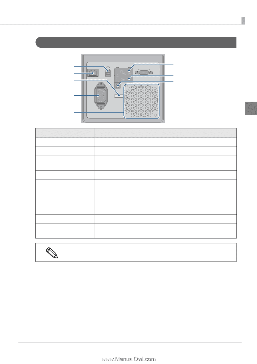
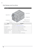
Rear Side Chapter 1 Product Overview USB Connector Ethernet Connector Wire Saddle AC Inlet Air Vent Dip Switch Cover Dip Switch Dip Switch Cover mounting screw 1 Name USB Connector Ethernet Connector Wire Saddle AC Inlet Air Vent Dip Switch Cover mounting screw Dip Switch Dip Switch Cover Description For connecting a USB cable. For connecting a LAN cable. Pass the USB cable through this saddle to prevent disconnection of the USB cable. For connecting a power cable. Exhausts heat generated in the product to prevent an internal temperature rise. Allow a clearance of 10 cm {3.94"} or more from the air vent to ensure ventilation when installing the product. Remove the screw to open the Dip Switch Cover. Used when changing the function of the Power button. When operating the Dip Switch, remove the Dip Switch Cover Mounting Screw and open the cover. When setting the Power button operation to "Power switch disabled (Reset operation)", make sure the printer is not operating when turning the power OFF. 21
-
 1
1 -
2
-
3
-
4
-
5
-
6
-
7
-
8
-
9
-
10
-
11
-
12
-
13
-
14
-
15
-
 16
16 -
 17
17 -
 18
18 -
 19
19 -
 20
20 -
 21
21 -
 22
22 -
 23
23 -
 24
24 -
 25
25 -
 26
26 -
27
-
28
-
29
-
30
-
31
-
32
-
33
-
34
-
35
-
36
-
37
-
38
-
39
-
40
-
41
-
42
-
43
-
44
-
45
-
46
-
47
-
48
-
49
-
50
-
51
-
52
-
53
-
54
-
55
-
56
-
57
-
58
-
59
-
60
-
61
-
62
-
63
-
64
-
65
-
66
-
67
-
68
-
69
-
70
-
71
-
72
-
73
-
74
-
75
-
76
-
77
-
78
-
79
-
80
-
81
-
82
-
83
-
84
-
85
-
86
-
87
-
88
-
89
-
90
-
91
-
92
-
93
-
94
-
95
-
96
-
97
-
98
-
99
-
100
-
101
-
102
-
103
-
104
-
105
-
106
-
107
-
108
-
109
-
110
-
111
-
112
-
113
-
114
-
115
-
116
-
117
-
118
-
119
-
120
-
121
-
122
-
123
-
124
-
125
-
126
-
127
-
128
-
129
-
130
-
131
-
132
-
133
-
134
-
135
-
136
-
137
-
138
-
139
-
140
-
141
-
142
-
143
-
144
-
145
-
146
-
147
-
148
-
149
-
150
-
151
-
152
-
153
-
154
-
155
-
156
-
157
-
158
-
159
-
160
-
161
-
162
-
163
-
164
-
165
-
166
-
167
-
168
-
169
-
170
-
171
-
172
-
173
-
174
-
175
-
176
-
177
-
178
-
179
-
180
-
181
-
182
-
183
-
184
-
185
-
186
-
187
-
188
-
189
-
190
-
191
-
192
-
193
-
194
-
195
-
196
-
197
-
198
-
199
-
200
-
201
-
202
-
203
-
204
-
205
-
206
-
207
-
208
-
209
-
210
-
211
-
212
-
213
-
214
-
215
-
216
-
217
-
218
-
219
-
220
-
221
-
222
-
223
-
224
 |
 |