Epson FX-185 User Manual - Page 182
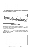
First version of 3D program
 |
View all Epson FX-185 manuals
Add to My Manuals
Save this manual to your list of manuals |
Page 182 highlights
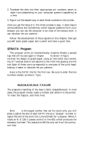
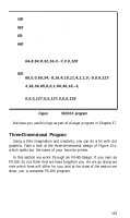
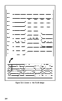
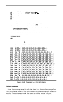
A very few pin patterns are needed for this program. In fact, each "pattern" consists of only one pin, making the numbers easy to calculate: 1 for the low pin 64 for the high pin 1, 2, 4, 8, 16, 32, 64 for the diagonal rise 64, 32, 16, 8, 4, 2, 1 for the diagonal fall As you will see in the next few pages, these pin patterns are coded right into the program. You'll only need to store as data the number of repetitions for the low and high sections. A close look at Figure 12-4 reveals that most of the lines can be produced by repeating a d-step pattern: 1. Fire the bottom pin (pin 1), repeat L times. 2. Draw a diagonal rise (pins 1 - 64). 3. Fire the top pin (pin 64), repeat H times. 4. Draw a diagonal fall (pins 64 - 1). This pattern is repeated several times. Printing the figure is mainly a matter of reading the length of the low and high sections, then printing the four-part cycle. First version of 3D program We have you enter this program in portions that are easy to discuss as units, so please don't try to RUN it until we give the word. Might as well start off with the easy stuff. Set the line spacing for 7pin graphics: NEW l0 LPRINT CHR$(27)"1" Note: If your system leaves gaps in 7-dot graphics printing, you will prefer to use the 6-2/3-dot line spacing, CHR$(27) "3'CHR$(20). Next up are the three straight lines at the start of the design. There's no need for anything fancy-just a single dot printed across the page. For that, add these lines (lines 20 and 170 are different for the FX-100): 29 G$=CHR$(27)+"L"+CHR$(51)+CHR$(3): GOSUB 160 158 LPRINT CHR$(27)"@": END 160 FOR X=1 TO 3: LPRINT G$; 165
-
 1
1 -
2
-
3
-
4
-
5
-
6
-
7
-
8
-
9
-
10
-
11
-
12
-
13
-
14
-
15
-
16
-
17
-
18
-
19
-
20
-
21
-
22
-
23
-
24
-
25
-
26
-
27
-
28
-
29
-
30
-
31
-
32
-
33
-
34
-
35
-
36
-
37
-
38
-
39
-
40
-
41
-
42
-
43
-
44
-
45
-
46
-
47
-
48
-
49
-
50
-
51
-
52
-
53
-
54
-
55
-
56
-
57
-
58
-
59
-
60
-
61
-
62
-
63
-
64
-
65
-
66
-
67
-
68
-
69
-
70
-
71
-
72
-
73
-
74
-
75
-
76
-
77
-
78
-
79
-
80
-
81
-
82
-
83
-
84
-
85
-
86
-
87
-
88
-
89
-
90
-
91
-
92
-
93
-
94
-
95
-
96
-
97
-
98
-
99
-
100
-
101
-
102
-
103
-
104
-
105
-
106
-
107
-
108
-
109
-
110
-
111
-
112
-
113
-
114
-
115
-
116
-
117
-
118
-
119
-
120
-
121
-
122
-
123
-
124
-
125
-
126
-
127
-
128
-
129
-
130
-
131
-
132
-
133
-
134
-
135
-
136
-
137
-
138
-
139
-
140
-
141
-
142
-
143
-
144
-
145
-
146
-
147
-
148
-
149
-
150
-
151
-
152
-
153
-
154
-
155
-
156
-
157
-
158
-
159
-
160
-
161
-
162
-
163
-
164
-
165
-
166
-
167
-
168
-
169
-
170
-
171
-
172
-
173
-
174
-
175
-
176
-
 177
177 -
 178
178 -
 179
179 -
 180
180 -
 181
181 -
 182
182 -
 183
183 -
 184
184 -
 185
185 -
 186
186 -
 187
187 -
188
-
189
-
190
-
191
-
192
-
193
-
194
-
195
-
196
-
197
-
198
-
199
-
200
-
201
-
202
-
203
-
204
-
205
-
206
-
207
-
208
-
209
-
210
-
211
-
212
-
213
-
214
-
215
-
216
-
217
-
218
-
219
-
220
-
221
-
222
-
223
-
224
-
225
-
226
-
227
-
228
-
229
-
230
-
231
-
232
-
233
-
234
-
235
-
236
-
237
-
238
-
239
-
240
-
241
-
242
-
243
-
244
-
245
-
246
-
247
-
248
-
249
-
250
-
251
-
252
-
253
-
254
-
255
-
256
-
257
-
258
-
259
-
260
-
261
-
262
-
263
-
264
-
265
-
266
-
267
-
268
 |
 |