Epson FX-185 User Manual - Page 218
Design, User-defined E
 |
View all Epson FX-185 manuals
Add to My Manuals
Save this manual to your list of manuals |
Page 218 highlights
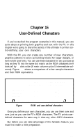
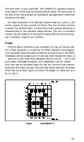
The semicolon is very important. The CHR$(27)"&" sequence expects more data to follow (just as Graphics Mode does). The semicolon at the end of the line prevents an unwanted carriage-return code from disrupting the data. For each character to be defined (determined by c1 and c2), the printer expects 12 data numbers to follow. The first of these numbers is called the attribute byte. It determines some special attributes or characteristics of the character being defined. The next 11 numbers contain the dot patterns of the symbol being defined-nothing fancy, just 11 standard graphics pin patterns. Design The first step in defining a new character is to lay out the dot pattern. Check Appendix A to see how the ROM characters are designed. Your characters share the same limitations as those found in the ROM. Characters can be a maximum of 8 dots tall (even though the matrix is 9 dots) and 11 dots wide. Most characters use only the top 7 pins of the print head; lowercase characters with descenders use the bottom 7. Also note that all characters leave the last two columns (one intermediate and one main) unused; this provides space between the letters when they are printed. Figure 15-2 shows the design of a letter E in an 8 by 11 matrix. Figure 15-2. User-defined E 201
-
 1
1 -
2
-
3
-
4
-
5
-
6
-
7
-
8
-
9
-
10
-
11
-
12
-
13
-
14
-
15
-
16
-
17
-
18
-
19
-
20
-
21
-
22
-
23
-
24
-
25
-
26
-
27
-
28
-
29
-
30
-
31
-
32
-
33
-
34
-
35
-
36
-
37
-
38
-
39
-
40
-
41
-
42
-
43
-
44
-
45
-
46
-
47
-
48
-
49
-
50
-
51
-
52
-
53
-
54
-
55
-
56
-
57
-
58
-
59
-
60
-
61
-
62
-
63
-
64
-
65
-
66
-
67
-
68
-
69
-
70
-
71
-
72
-
73
-
74
-
75
-
76
-
77
-
78
-
79
-
80
-
81
-
82
-
83
-
84
-
85
-
86
-
87
-
88
-
89
-
90
-
91
-
92
-
93
-
94
-
95
-
96
-
97
-
98
-
99
-
100
-
101
-
102
-
103
-
104
-
105
-
106
-
107
-
108
-
109
-
110
-
111
-
112
-
113
-
114
-
115
-
116
-
117
-
118
-
119
-
120
-
121
-
122
-
123
-
124
-
125
-
126
-
127
-
128
-
129
-
130
-
131
-
132
-
133
-
134
-
135
-
136
-
137
-
138
-
139
-
140
-
141
-
142
-
143
-
144
-
145
-
146
-
147
-
148
-
149
-
150
-
151
-
152
-
153
-
154
-
155
-
156
-
157
-
158
-
159
-
160
-
161
-
162
-
163
-
164
-
165
-
166
-
167
-
168
-
169
-
170
-
171
-
172
-
173
-
174
-
175
-
176
-
177
-
178
-
179
-
180
-
181
-
182
-
183
-
184
-
185
-
186
-
187
-
188
-
189
-
190
-
191
-
192
-
193
-
194
-
195
-
196
-
197
-
198
-
199
-
200
-
201
-
202
-
203
-
204
-
205
-
206
-
207
-
208
-
209
-
210
-
211
-
212
-
 213
213 -
 214
214 -
 215
215 -
 216
216 -
 217
217 -
 218
218 -
 219
219 -
 220
220 -
 221
221 -
 222
222 -
 223
223 -
224
-
225
-
226
-
227
-
228
-
229
-
230
-
231
-
232
-
233
-
234
-
235
-
236
-
237
-
238
-
239
-
240
-
241
-
242
-
243
-
244
-
245
-
246
-
247
-
248
-
249
-
250
-
251
-
252
-
253
-
254
-
255
-
256
-
257
-
258
-
259
-
260
-
261
-
262
-
263
-
264
-
265
-
266
-
267
-
268
 |
 |
