HP LaserJet 3052 Service Manual - Page 110
Scanner operation, ADF operation, Standby paper-loading mode
 |
View all HP LaserJet 3052 manuals
Add to My Manuals
Save this manual to your list of manuals |
Page 110 highlights
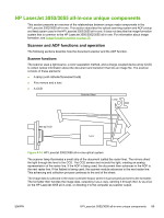
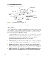
The image data CCD sensor uses a 300 ppi array and two half-pixel-offset 600 ppi arrays which are capable of collecting data at 600 ppi or 1200 ppi (600 ppi if one array is used or 1200 ppi if both arrays are used). Scanner operation At startup and periodically at other times, the scanner assembly moves systematically to locate its home position. It then calibrates to a white strip located under the glass at the right end of the scan tub. If the all-in-one detects a document in the ADF when a copy or scan is initiated (from the software or the control panel), the scan module moves to the left side of the scan tub and stops. The image is acquired as the paper is fed through the ADF past the scanner module. If no document is detected in the ADF, or if the model does not have an ADF, the scan module acquires the image from the flatbed glass while slowly moving within the scan tub. ADF operation Standby (paper-loading) mode: In standby mode, the pickup roller is up and the stack-stop is down, preventing the user from inserting the original document too far. When a document is inserted correctly, the paper-present sensor detects its presence. The standard operation of the ADF consists of the pick, feed, and lift steps. Pick: When it receives a copy or scan command, the ADF motor engages the gear train to lower the pickup-roller assembly and raise the stack-stop. The first roller, called the pre-pick roller, moves the top few sheets forward into the ADF. The next roller is the pickup roller. This roller contacts the ADF separation pad, which separates multiple pages into single sheets. Feed: The single sheet continues through the path. Along the way, the form sensor, which is a set distance from the ADF glass, detects the sheet. This alerts the scanner to start when the page reaches the glass. The scanner acquires the image, one raster line at a time, until it detects the end of the page. The page is then ejected. The pick and feed steps are repeated as long as paper is detected in the ADF input tray. Lift: When no more paper is detected in the ADF input tray and the form sensor detects the trailing edge of the last page, the last sheet is ejected and the motor turns in a sequence that lifts the pick roller assembly to standby (paper-loading) mode again. The ADF will not function when the ADF lid is open. The paper path is incomplete if the ADF lid is lifted from the glass. 90 Chapter 4 Theory of operation ENWW
-
 1
1 -
2
-
3
-
4
-
5
-
6
-
7
-
8
-
9
-
10
-
11
-
12
-
13
-
14
-
15
-
16
-
17
-
18
-
19
-
20
-
21
-
22
-
23
-
24
-
25
-
26
-
27
-
28
-
29
-
30
-
31
-
32
-
33
-
34
-
35
-
36
-
37
-
38
-
39
-
40
-
41
-
42
-
43
-
44
-
45
-
46
-
47
-
48
-
49
-
50
-
51
-
52
-
53
-
54
-
55
-
56
-
57
-
58
-
59
-
60
-
61
-
62
-
63
-
64
-
65
-
66
-
67
-
68
-
69
-
70
-
71
-
72
-
73
-
74
-
75
-
76
-
77
-
78
-
79
-
80
-
81
-
82
-
83
-
84
-
85
-
86
-
87
-
88
-
89
-
90
-
91
-
92
-
93
-
94
-
95
-
96
-
97
-
98
-
99
-
100
-
101
-
102
-
103
-
104
-
 105
105 -
 106
106 -
 107
107 -
 108
108 -
 109
109 -
 110
110 -
 111
111 -
 112
112 -
 113
113 -
 114
114 -
 115
115 -
116
-
117
-
118
-
119
-
120
-
121
-
122
-
123
-
124
-
125
-
126
-
127
-
128
-
129
-
130
-
131
-
132
-
133
-
134
-
135
-
136
-
137
-
138
-
139
-
140
-
141
-
142
-
143
-
144
-
145
-
146
-
147
-
148
-
149
-
150
-
151
-
152
-
153
-
154
-
155
-
156
-
157
-
158
-
159
-
160
-
161
-
162
-
163
-
164
-
165
-
166
-
167
-
168
-
169
-
170
-
171
-
172
-
173
-
174
-
175
-
176
-
177
-
178
-
179
-
180
-
181
-
182
-
183
-
184
-
185
-
186
-
187
-
188
-
189
-
190
-
191
-
192
-
193
-
194
-
195
-
196
-
197
-
198
-
199
-
200
-
201
-
202
-
203
-
204
-
205
-
206
-
207
-
208
-
209
-
210
-
211
-
212
-
213
-
214
-
215
-
216
-
217
-
218
-
219
-
220
-
221
-
222
-
223
-
224
-
225
-
226
-
227
-
228
-
229
-
230
-
231
-
232
-
233
-
234
-
235
-
236
-
237
-
238
-
239
-
240
-
241
-
242
-
243
-
244
-
245
-
246
-
247
-
248
-
249
-
250
-
251
-
252
-
253
-
254
-
255
-
256
-
257
-
258
-
259
-
260
-
261
-
262
-
263
-
264
-
265
-
266
-
267
-
268
-
269
-
270
-
271
-
272
-
273
-
274
-
275
-
276
-
277
-
278
-
279
-
280
-
281
-
282
-
283
-
284
-
285
-
286
-
287
-
288
-
289
-
290
-
291
-
292
-
293
-
294
-
295
-
296
-
297
-
298
-
299
-
300
-
301
-
302
-
303
-
304
-
305
-
306
-
307
-
308
-
309
-
310
-
311
-
312
-
313
-
314
-
315
-
316
-
317
-
318
-
319
-
320
-
321
-
322
-
323
-
324
-
325
-
326
-
327
-
328
-
329
-
330
-
331
-
332
-
333
-
334
-
335
-
336
-
337
-
338
-
339
-
340
-
341
-
342
-
343
-
344
-
345
-
346
-
347
-
348
-
349
-
350
-
351
-
352
-
353
-
354
-
355
-
356
-
357
-
358
-
359
-
360
-
361
-
362
-
363
-
364
-
365
-
366
-
367
-
368
-
369
-
370
-
371
-
372
-
373
-
374
-
375
-
376
-
377
-
378
-
379
-
380
-
381
-
382
-
383
-
384
-
385
-
386
-
387
-
388
-
389
-
390
-
391
-
392
-
393
-
394
-
395
-
396
-
397
-
398
-
399
-
400
-
401
-
402
-
403
-
404
-
405
-
406
 |
 |