HP Z600 HP Z600 Workstation Maintenance and Service Guide - Page 100
Power switch cable assembly, Removing the power switch cable assembly
 |
UPC - 884962074053
View all HP Z600 manuals
Add to My Manuals
Save this manual to your list of manuals |
Page 100 highlights
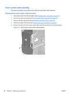
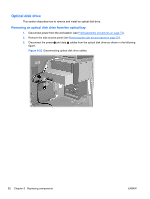
Power switch cable assembly This section describes how to remove and install the power switch cable assembly. Removing the power switch cable assembly 1. Disconnect power from the workstation (see Predisassembly procedures on page 73). 2. Remove the side access panel (see Removing the side access panel on page 75). 3. Remove the right side panel (see Removing the right side panel on page 78). 4. Remove the upper front bezel (see Removing the upper front bezel on page 83). 5. Remove the screw from the power switch cable assembly as shown in the following figure. Figure 5-17 Removing the power switch cable assembly 88 Chapter 5 Replacing components ENWW
-
 1
1 -
2
-
3
-
4
-
5
-
6
-
7
-
8
-
9
-
10
-
11
-
12
-
13
-
14
-
15
-
16
-
17
-
18
-
19
-
20
-
21
-
22
-
23
-
24
-
25
-
26
-
27
-
28
-
29
-
30
-
31
-
32
-
33
-
34
-
35
-
36
-
37
-
38
-
39
-
40
-
41
-
42
-
43
-
44
-
45
-
46
-
47
-
48
-
49
-
50
-
51
-
52
-
53
-
54
-
55
-
56
-
57
-
58
-
59
-
60
-
61
-
62
-
63
-
64
-
65
-
66
-
67
-
68
-
69
-
70
-
71
-
72
-
73
-
74
-
75
-
76
-
77
-
78
-
79
-
80
-
81
-
82
-
83
-
84
-
85
-
86
-
87
-
88
-
89
-
90
-
91
-
92
-
93
-
94
-
 95
95 -
 96
96 -
 97
97 -
 98
98 -
 99
99 -
 100
100 -
 101
101 -
 102
102 -
 103
103 -
 104
104 -
 105
105 -
106
-
107
-
108
-
109
-
110
-
111
-
112
-
113
-
114
-
115
-
116
-
117
-
118
-
119
-
120
-
121
-
122
-
123
-
124
-
125
-
126
-
127
-
128
-
129
-
130
-
131
-
132
-
133
-
134
-
135
-
136
-
137
-
138
-
139
-
140
-
141
-
142
-
143
-
144
-
145
-
146
-
147
-
148
-
149
-
150
-
151
-
152
-
153
-
154
-
155
-
156
-
157
-
158
-
159
-
160
-
161
-
162
-
163
-
164
-
165
-
166
-
167
-
168
-
169
-
170
-
171
-
172
-
173
-
174
-
175
-
176
-
177
-
178
-
179
-
180
-
181
-
182
-
183
-
184
-
185
-
186
-
187
-
188
-
189
-
190
-
191
-
192
-
193
-
194
-
195
-
196
-
197
-
198
-
199
-
200
-
201
-
202
-
203
-
204
-
205
-
206
-
207
-
208
-
209
-
210
-
211
-
212
-
213
-
214
-
215
-
216
-
217
-
218
-
219
-
220
-
221
-
222
-
223
-
224
-
225
-
226
-
227
-
228
-
229
-
230
-
231
-
232
-
233
-
234
-
235
-
236
-
237
 |
 |
Power switch cable assembly
This section describes how to remove and install the power switch cable assembly.
Removing the power switch cable assembly
1.
Disconnect power from the workstation (see
Predisassembly procedures
on page
73
).
2.
Remove the side access panel (see
Removing the side access panel
on page
75
).
3.
Remove the right side panel (see
Removing the right side panel
on page
78
).
4.
Remove the upper front bezel (see
Removing the upper front bezel
on page
83
).
5.
Remove the screw from the power switch cable assembly as shown in the following figure.
Figure 5-17
Removing the power switch cable assembly
88
Chapter 5
Replacing components
ENWW