HP Z600 HP Z600 Workstation Maintenance and Service Guide - Page 93
Installing the side access panel sensor, Power connections
 |
UPC - 884962074053
View all HP Z600 manuals
Add to My Manuals
Save this manual to your list of manuals |
Page 93 highlights
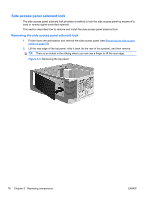
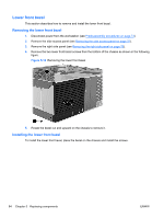
4. Disconnect the sensor cable from the inline chassis cable as shown in the following figure . Figure 5-9 Removing the side access panel sensor 5. Slide the sensor back in its slot, push the sensor down, and then remove it from the chassis 2 as shown above. Installing the side access panel sensor To replace the side access panel sensor, reverse the removal steps. NOTE: The cable must be looped and stored in the cable clip provided to ensure it is not in the power supply sliding zone. Power connections For help with identifying power cables, see the following figure and table. Ensure that all cables are routed or tied so they cannot interfere with the processor heatsink fans. ENWW Removing and installing components 81
-
 1
1 -
2
-
3
-
4
-
5
-
6
-
7
-
8
-
9
-
10
-
11
-
12
-
13
-
14
-
15
-
16
-
17
-
18
-
19
-
20
-
21
-
22
-
23
-
24
-
25
-
26
-
27
-
28
-
29
-
30
-
31
-
32
-
33
-
34
-
35
-
36
-
37
-
38
-
39
-
40
-
41
-
42
-
43
-
44
-
45
-
46
-
47
-
48
-
49
-
50
-
51
-
52
-
53
-
54
-
55
-
56
-
57
-
58
-
59
-
60
-
61
-
62
-
63
-
64
-
65
-
66
-
67
-
68
-
69
-
70
-
71
-
72
-
73
-
74
-
75
-
76
-
77
-
78
-
79
-
80
-
81
-
82
-
83
-
84
-
85
-
86
-
87
-
 88
88 -
 89
89 -
 90
90 -
 91
91 -
 92
92 -
 93
93 -
 94
94 -
 95
95 -
 96
96 -
 97
97 -
 98
98 -
99
-
100
-
101
-
102
-
103
-
104
-
105
-
106
-
107
-
108
-
109
-
110
-
111
-
112
-
113
-
114
-
115
-
116
-
117
-
118
-
119
-
120
-
121
-
122
-
123
-
124
-
125
-
126
-
127
-
128
-
129
-
130
-
131
-
132
-
133
-
134
-
135
-
136
-
137
-
138
-
139
-
140
-
141
-
142
-
143
-
144
-
145
-
146
-
147
-
148
-
149
-
150
-
151
-
152
-
153
-
154
-
155
-
156
-
157
-
158
-
159
-
160
-
161
-
162
-
163
-
164
-
165
-
166
-
167
-
168
-
169
-
170
-
171
-
172
-
173
-
174
-
175
-
176
-
177
-
178
-
179
-
180
-
181
-
182
-
183
-
184
-
185
-
186
-
187
-
188
-
189
-
190
-
191
-
192
-
193
-
194
-
195
-
196
-
197
-
198
-
199
-
200
-
201
-
202
-
203
-
204
-
205
-
206
-
207
-
208
-
209
-
210
-
211
-
212
-
213
-
214
-
215
-
216
-
217
-
218
-
219
-
220
-
221
-
222
-
223
-
224
-
225
-
226
-
227
-
228
-
229
-
230
-
231
-
232
-
233
-
234
-
235
-
236
-
237
 |
 |
4.
Disconnect the sensor cable from the inline chassis cable as shown in the following figure
.
Figure 5-9
Removing the side access panel sensor
5.
Slide the sensor back in its slot, push the sensor down, and then remove it from the chassis
2
as
shown above.
Installing the side access panel sensor
To replace the side access panel sensor, reverse the removal steps.
NOTE:
The cable must be looped and stored in the cable clip provided to ensure it is not in the power
supply sliding zone.
Power connections
For help with identifying power cables, see the following figure and table. Ensure that all cables are
routed or tied so they cannot interfere with the processor heatsink fans.
ENWW
Removing and installing components
81