HP Z600 HP Z600 Workstation Maintenance and Service Guide - Page 226
System board designators, Designator, Silk screen, Component
 |
UPC - 884962074053
View all HP Z600 manuals
Add to My Manuals
Save this manual to your list of manuals |
Page 226 highlights
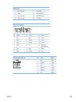
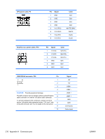
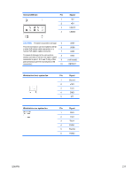
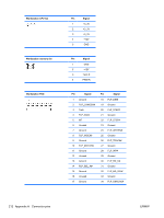
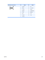
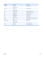
B System board designators This appendix describes the system board designators for this workstation. Designator MTG1-MTG10 E15 E49 J9 J10 J20 J21 J31 J32 J41 J42 J68 J81 J83 J86 J87 SW50 P1 P2 P3 P5 P7 P8 P24 P26 P27 P29 Silk screen N/A E15 E49 J9 RJ45/QUAD USB J10 Quad USB J20 SLOT5 PCI J21 SLOT6 PCI J31 SLOT1 PCIe2 x8(4) J32 SLOT3 PCIe x8(4) J41 SLOT2 PCIe2 x16 75W J42 SLOT4 PCIe2 x16 75W J68 PS2 J81 1394/USB J83 AUDIO J86 J87 SW50 CMOS P1PWR MAIN P2 PWR MEM P3 PWR CPU P5 PB/LED P7 FDD P8 REAR FANS P24 FRONT USB P26 INTERNAL USB2/DASH P27 INTERNAL USB1 P29 Component Mounting holes Crisis recovery header/jumper Clear password header/jumper RJ-45 Quad rear USB PCI slot PCI slot PCIe2 x8(4) slot PCIe x8(4) slot PCIe2 x16 slot PCIe2 x16 slot Stacked keyboard/mouse connector Stacked/dual USB Triple stacked audio jacks Slot2 PCIe x16 retention clip Slot4 PCIe x16 retention clip Clear CMOS switch/push button Main power connector (18-pin) Memory power connector (6-pin) CPU power connector (8-pin) Power button/HDD LED/Power LED switch/ Side access panel sensor/Temperature header Flexible disk drive Rear system fan Front panel USB header DASH/Dual internal USB Single USB header Hard disk drive LED connector 214 Appendix B System board designators ENWW
-
 1
1 -
2
-
3
-
4
-
5
-
6
-
7
-
8
-
9
-
10
-
11
-
12
-
13
-
14
-
15
-
16
-
17
-
18
-
19
-
20
-
21
-
22
-
23
-
24
-
25
-
26
-
27
-
28
-
29
-
30
-
31
-
32
-
33
-
34
-
35
-
36
-
37
-
38
-
39
-
40
-
41
-
42
-
43
-
44
-
45
-
46
-
47
-
48
-
49
-
50
-
51
-
52
-
53
-
54
-
55
-
56
-
57
-
58
-
59
-
60
-
61
-
62
-
63
-
64
-
65
-
66
-
67
-
68
-
69
-
70
-
71
-
72
-
73
-
74
-
75
-
76
-
77
-
78
-
79
-
80
-
81
-
82
-
83
-
84
-
85
-
86
-
87
-
88
-
89
-
90
-
91
-
92
-
93
-
94
-
95
-
96
-
97
-
98
-
99
-
100
-
101
-
102
-
103
-
104
-
105
-
106
-
107
-
108
-
109
-
110
-
111
-
112
-
113
-
114
-
115
-
116
-
117
-
118
-
119
-
120
-
121
-
122
-
123
-
124
-
125
-
126
-
127
-
128
-
129
-
130
-
131
-
132
-
133
-
134
-
135
-
136
-
137
-
138
-
139
-
140
-
141
-
142
-
143
-
144
-
145
-
146
-
147
-
148
-
149
-
150
-
151
-
152
-
153
-
154
-
155
-
156
-
157
-
158
-
159
-
160
-
161
-
162
-
163
-
164
-
165
-
166
-
167
-
168
-
169
-
170
-
171
-
172
-
173
-
174
-
175
-
176
-
177
-
178
-
179
-
180
-
181
-
182
-
183
-
184
-
185
-
186
-
187
-
188
-
189
-
190
-
191
-
192
-
193
-
194
-
195
-
196
-
197
-
198
-
199
-
200
-
201
-
202
-
203
-
204
-
205
-
206
-
207
-
208
-
209
-
210
-
211
-
212
-
213
-
214
-
215
-
216
-
217
-
218
-
219
-
220
-
 221
221 -
 222
222 -
 223
223 -
 224
224 -
 225
225 -
 226
226 -
 227
227 -
 228
228 -
 229
229 -
 230
230 -
 231
231 -
232
-
233
-
234
-
235
-
236
-
237
 |
 |