HP Z600 HP Z600 Workstation Maintenance and Service Guide - Page 101
Installing the power switch cable assembly, Optical bay filler tray
 |
UPC - 884962074053
View all HP Z600 manuals
Add to My Manuals
Save this manual to your list of manuals |
Page 101 highlights
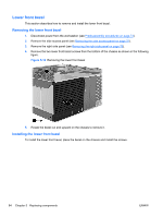
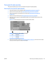
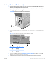
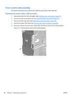
6. Disconnect the power switch cable assembly cable from the system board as shown in the following figure. Figure 5-18 Disconnecting the power switch cable assembly cable 7. Carefully guide the cable out of the chassis from its location behind the right side panel as shown in the following figure. Figure 5-19 Removing the power switch cable Installing the power switch cable assembly To replace the power switch cable assembly, reverse the removal steps. Optical bay filler tray If an optical bay slot is left empty, a filler tray must be placed in the slot to ensure proper electromagnetic interference (EMI) protection and cooling air efficiency. ENWW Removing and installing components 89
-
 1
1 -
2
-
3
-
4
-
5
-
6
-
7
-
8
-
9
-
10
-
11
-
12
-
13
-
14
-
15
-
16
-
17
-
18
-
19
-
20
-
21
-
22
-
23
-
24
-
25
-
26
-
27
-
28
-
29
-
30
-
31
-
32
-
33
-
34
-
35
-
36
-
37
-
38
-
39
-
40
-
41
-
42
-
43
-
44
-
45
-
46
-
47
-
48
-
49
-
50
-
51
-
52
-
53
-
54
-
55
-
56
-
57
-
58
-
59
-
60
-
61
-
62
-
63
-
64
-
65
-
66
-
67
-
68
-
69
-
70
-
71
-
72
-
73
-
74
-
75
-
76
-
77
-
78
-
79
-
80
-
81
-
82
-
83
-
84
-
85
-
86
-
87
-
88
-
89
-
90
-
91
-
92
-
93
-
94
-
95
-
 96
96 -
 97
97 -
 98
98 -
 99
99 -
 100
100 -
 101
101 -
 102
102 -
 103
103 -
 104
104 -
 105
105 -
 106
106 -
107
-
108
-
109
-
110
-
111
-
112
-
113
-
114
-
115
-
116
-
117
-
118
-
119
-
120
-
121
-
122
-
123
-
124
-
125
-
126
-
127
-
128
-
129
-
130
-
131
-
132
-
133
-
134
-
135
-
136
-
137
-
138
-
139
-
140
-
141
-
142
-
143
-
144
-
145
-
146
-
147
-
148
-
149
-
150
-
151
-
152
-
153
-
154
-
155
-
156
-
157
-
158
-
159
-
160
-
161
-
162
-
163
-
164
-
165
-
166
-
167
-
168
-
169
-
170
-
171
-
172
-
173
-
174
-
175
-
176
-
177
-
178
-
179
-
180
-
181
-
182
-
183
-
184
-
185
-
186
-
187
-
188
-
189
-
190
-
191
-
192
-
193
-
194
-
195
-
196
-
197
-
198
-
199
-
200
-
201
-
202
-
203
-
204
-
205
-
206
-
207
-
208
-
209
-
210
-
211
-
212
-
213
-
214
-
215
-
216
-
217
-
218
-
219
-
220
-
221
-
222
-
223
-
224
-
225
-
226
-
227
-
228
-
229
-
230
-
231
-
232
-
233
-
234
-
235
-
236
-
237
 |
 |
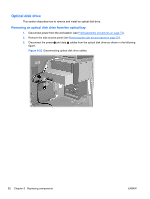
6.
Disconnect the power switch cable assembly cable from the system board as shown in the following
figure.
Figure 5-18
Disconnecting the power switch cable assembly cable
7.
Carefully guide the cable out of the chassis from its location behind the right side panel as shown
in the following figure.
Figure 5-19
Removing the power switch cable
Installing the power switch cable assembly
To replace the power switch cable assembly, reverse the removal steps.
Optical bay filler tray
If an optical bay slot is left empty, a filler tray must be placed in the slot to ensure proper electromagnetic
interference (EMI) protection and cooling air efficiency.
ENWW
Removing and installing components
89