HP Z600 HP Z600 Workstation Maintenance and Service Guide - Page 114
Hard disk drive,
 |
UPC - 884962074053
View all HP Z600 manuals
Add to My Manuals
Save this manual to your list of manuals |
Page 114 highlights
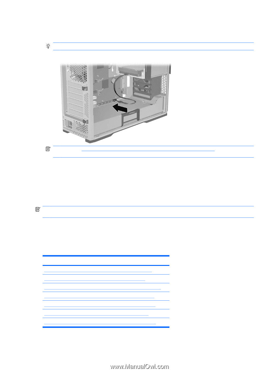
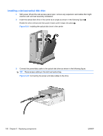
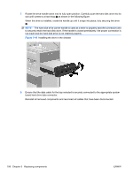
6. Connect the optical disk drive data cable to the system board connector as shown in the following figure. TIP: Route the data cable along the system board. Figure 5-35 Connecting the data cable to the system board NOTE: See Installing a hard disk drive in the slot load optical bay on page 109 if you are installing a hard disk drive in the slot load optical bay. 7. Reassemble the workstation, and then replace the side access cover. Hard disk drive This workstation accommodates both SAS and SATA hard drives. Both 3.5 in. standard hard disk drives or 2.5 in. small form factor (SFF) hard disk drives may be installed in the workstation. NOTE: A 2.5 in. hard drive must be mounted in a 3.5 in. adapter before it can be installed in the chassis blind-mate carrier. Hard disk drives can be installed in the hard drive bay and the optical drive bay. Drives should be installed in the hard drive bay first, then in the optical drive bay. Installation in the optical drive bay requires an optional adapter kit. The hard drives blind-mate (direct-connect) to chassis mounted connectors, so manual cable connections may be avoided. Topic Removing a hard disk drive from the hard drive bay on page 103 Installing a hard disk drive in the hard drive bay on page 104 Removing a hard disk drive from the slot load optical bay on page 107 Installing a hard disk drive in the slot load optical bay on page 109 Removing a hard disk drive from the optical drive bay on page 113 Installing a hard disk drive in the optical drive bay on page 115 Installing dual SFF hard drives in the optical drive bay on page 117 102 Chapter 5 Replacing components ENWW
-
 1
1 -
2
-
3
-
4
-
5
-
6
-
7
-
8
-
9
-
10
-
11
-
12
-
13
-
14
-
15
-
16
-
17
-
18
-
19
-
20
-
21
-
22
-
23
-
24
-
25
-
26
-
27
-
28
-
29
-
30
-
31
-
32
-
33
-
34
-
35
-
36
-
37
-
38
-
39
-
40
-
41
-
42
-
43
-
44
-
45
-
46
-
47
-
48
-
49
-
50
-
51
-
52
-
53
-
54
-
55
-
56
-
57
-
58
-
59
-
60
-
61
-
62
-
63
-
64
-
65
-
66
-
67
-
68
-
69
-
70
-
71
-
72
-
73
-
74
-
75
-
76
-
77
-
78
-
79
-
80
-
81
-
82
-
83
-
84
-
85
-
86
-
87
-
88
-
89
-
90
-
91
-
92
-
93
-
94
-
95
-
96
-
97
-
98
-
99
-
100
-
101
-
102
-
103
-
104
-
105
-
106
-
107
-
108
-
 109
109 -
 110
110 -
 111
111 -
 112
112 -
 113
113 -
 114
114 -
 115
115 -
 116
116 -
 117
117 -
 118
118 -
 119
119 -
120
-
121
-
122
-
123
-
124
-
125
-
126
-
127
-
128
-
129
-
130
-
131
-
132
-
133
-
134
-
135
-
136
-
137
-
138
-
139
-
140
-
141
-
142
-
143
-
144
-
145
-
146
-
147
-
148
-
149
-
150
-
151
-
152
-
153
-
154
-
155
-
156
-
157
-
158
-
159
-
160
-
161
-
162
-
163
-
164
-
165
-
166
-
167
-
168
-
169
-
170
-
171
-
172
-
173
-
174
-
175
-
176
-
177
-
178
-
179
-
180
-
181
-
182
-
183
-
184
-
185
-
186
-
187
-
188
-
189
-
190
-
191
-
192
-
193
-
194
-
195
-
196
-
197
-
198
-
199
-
200
-
201
-
202
-
203
-
204
-
205
-
206
-
207
-
208
-
209
-
210
-
211
-
212
-
213
-
214
-
215
-
216
-
217
-
218
-
219
-
220
-
221
-
222
-
223
-
224
-
225
-
226
-
227
-
228
-
229
-
230
-
231
-
232
-
233
-
234
-
235
-
236
-
237
 |
 |