HP Z600 HP Z600 Workstation Maintenance and Service Guide - Page 122
HP Z600 - Workstation - 6 GB RAM Manual
 |
UPC - 884962074053
View all HP Z600 manuals
Add to My Manuals
Save this manual to your list of manuals |
Page 122 highlights
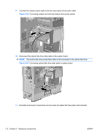
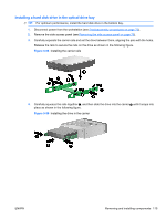
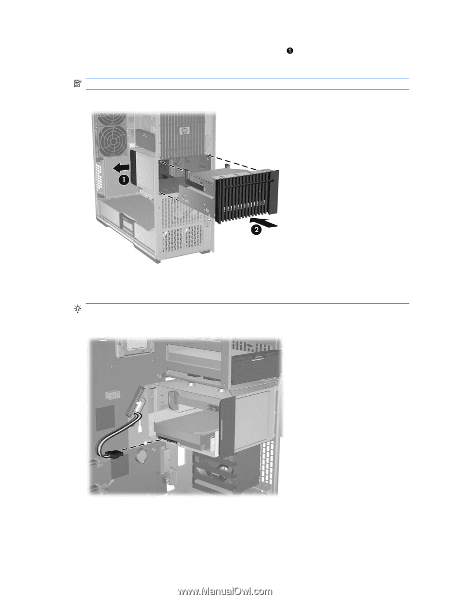
5. Lift and hold the drive release latch at the green touch point while sliding the slot load carrier into the bay. When the front of the carrier is near its final position, release the latch, but continue to slide the carrier inward until the latch closes and engages the carrier 2. NOTE: Install the slot load optical bay with the slot load drive at the top. Figure 5-48 Installing the slot load carrier in the chassis 6. Connect the chassis power cable to the hard disk drive power connector as shown in the following figure. TIP: Place excess cabling in the slot load bay. Figure 5-49 Connecting chassis power cable to hard disk drive connector 110 Chapter 5 Replacing components ENWW
-
 1
1 -
2
-
3
-
4
-
5
-
6
-
7
-
8
-
9
-
10
-
11
-
12
-
13
-
14
-
15
-
16
-
17
-
18
-
19
-
20
-
21
-
22
-
23
-
24
-
25
-
26
-
27
-
28
-
29
-
30
-
31
-
32
-
33
-
34
-
35
-
36
-
37
-
38
-
39
-
40
-
41
-
42
-
43
-
44
-
45
-
46
-
47
-
48
-
49
-
50
-
51
-
52
-
53
-
54
-
55
-
56
-
57
-
58
-
59
-
60
-
61
-
62
-
63
-
64
-
65
-
66
-
67
-
68
-
69
-
70
-
71
-
72
-
73
-
74
-
75
-
76
-
77
-
78
-
79
-
80
-
81
-
82
-
83
-
84
-
85
-
86
-
87
-
88
-
89
-
90
-
91
-
92
-
93
-
94
-
95
-
96
-
97
-
98
-
99
-
100
-
101
-
102
-
103
-
104
-
105
-
106
-
107
-
108
-
109
-
110
-
111
-
112
-
113
-
114
-
115
-
116
-
 117
117 -
 118
118 -
 119
119 -
 120
120 -
 121
121 -
 122
122 -
 123
123 -
 124
124 -
 125
125 -
 126
126 -
 127
127 -
128
-
129
-
130
-
131
-
132
-
133
-
134
-
135
-
136
-
137
-
138
-
139
-
140
-
141
-
142
-
143
-
144
-
145
-
146
-
147
-
148
-
149
-
150
-
151
-
152
-
153
-
154
-
155
-
156
-
157
-
158
-
159
-
160
-
161
-
162
-
163
-
164
-
165
-
166
-
167
-
168
-
169
-
170
-
171
-
172
-
173
-
174
-
175
-
176
-
177
-
178
-
179
-
180
-
181
-
182
-
183
-
184
-
185
-
186
-
187
-
188
-
189
-
190
-
191
-
192
-
193
-
194
-
195
-
196
-
197
-
198
-
199
-
200
-
201
-
202
-
203
-
204
-
205
-
206
-
207
-
208
-
209
-
210
-
211
-
212
-
213
-
214
-
215
-
216
-
217
-
218
-
219
-
220
-
221
-
222
-
223
-
224
-
225
-
226
-
227
-
228
-
229
-
230
-
231
-
232
-
233
-
234
-
235
-
236
-
237
 |
 |
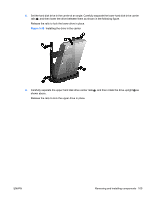
5.
Lift and hold the drive release latch at the green touch point
while sliding the slot load carrier
into the bay. When the front of the carrier is near its final position, release the latch, but continue
to slide the carrier inward until the latch closes and engages the carrier
2
.
NOTE:
Install the slot load optical bay with the slot load drive at the top.
Figure 5-48
Installing the slot load carrier in the chassis
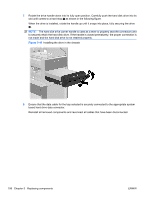
6.
Connect the chassis power cable to the hard disk drive power connector as shown in the following
figure.
TIP:
Place excess cabling in the slot load bay.
Figure 5-49
Connecting chassis power cable to hard disk drive connector
110
Chapter 5
Replacing components
ENWW