HP Z600 HP Z600 Workstation Maintenance and Service Guide - Page 94
For help with identifying power cables
 |
UPC - 884962074053
View all HP Z600 manuals
Add to My Manuals
Save this manual to your list of manuals |
Page 94 highlights
For help with identifying power cables, see the following figure and table. Ensure that all cables are routed or tied so they cannot interfere with the processor heatsink fans. Figure 5-10 Power connector identification for a typical configuration Table 5-4 Power connector description Item Description P1 Main power P2 Memory power P3 Memory power P4 SATA power P5 SATA power P6 IDE power P7 FDD power Item P10 P24 P25 A B C Description Graphics power Power to main and drives Power to CPU and memory Power supply HDD bay 0 HDD bay 1 82 Chapter 5 Replacing components ENWW
-
 1
1 -
2
-
3
-
4
-
5
-
6
-
7
-
8
-
9
-
10
-
11
-
12
-
13
-
14
-
15
-
16
-
17
-
18
-
19
-
20
-
21
-
22
-
23
-
24
-
25
-
26
-
27
-
28
-
29
-
30
-
31
-
32
-
33
-
34
-
35
-
36
-
37
-
38
-
39
-
40
-
41
-
42
-
43
-
44
-
45
-
46
-
47
-
48
-
49
-
50
-
51
-
52
-
53
-
54
-
55
-
56
-
57
-
58
-
59
-
60
-
61
-
62
-
63
-
64
-
65
-
66
-
67
-
68
-
69
-
70
-
71
-
72
-
73
-
74
-
75
-
76
-
77
-
78
-
79
-
80
-
81
-
82
-
83
-
84
-
85
-
86
-
87
-
88
-
 89
89 -
 90
90 -
 91
91 -
 92
92 -
 93
93 -
 94
94 -
 95
95 -
 96
96 -
 97
97 -
 98
98 -
 99
99 -
100
-
101
-
102
-
103
-
104
-
105
-
106
-
107
-
108
-
109
-
110
-
111
-
112
-
113
-
114
-
115
-
116
-
117
-
118
-
119
-
120
-
121
-
122
-
123
-
124
-
125
-
126
-
127
-
128
-
129
-
130
-
131
-
132
-
133
-
134
-
135
-
136
-
137
-
138
-
139
-
140
-
141
-
142
-
143
-
144
-
145
-
146
-
147
-
148
-
149
-
150
-
151
-
152
-
153
-
154
-
155
-
156
-
157
-
158
-
159
-
160
-
161
-
162
-
163
-
164
-
165
-
166
-
167
-
168
-
169
-
170
-
171
-
172
-
173
-
174
-
175
-
176
-
177
-
178
-
179
-
180
-
181
-
182
-
183
-
184
-
185
-
186
-
187
-
188
-
189
-
190
-
191
-
192
-
193
-
194
-
195
-
196
-
197
-
198
-
199
-
200
-
201
-
202
-
203
-
204
-
205
-
206
-
207
-
208
-
209
-
210
-
211
-
212
-
213
-
214
-
215
-
216
-
217
-
218
-
219
-
220
-
221
-
222
-
223
-
224
-
225
-
226
-
227
-
228
-
229
-
230
-
231
-
232
-
233
-
234
-
235
-
236
-
237
 |
 |
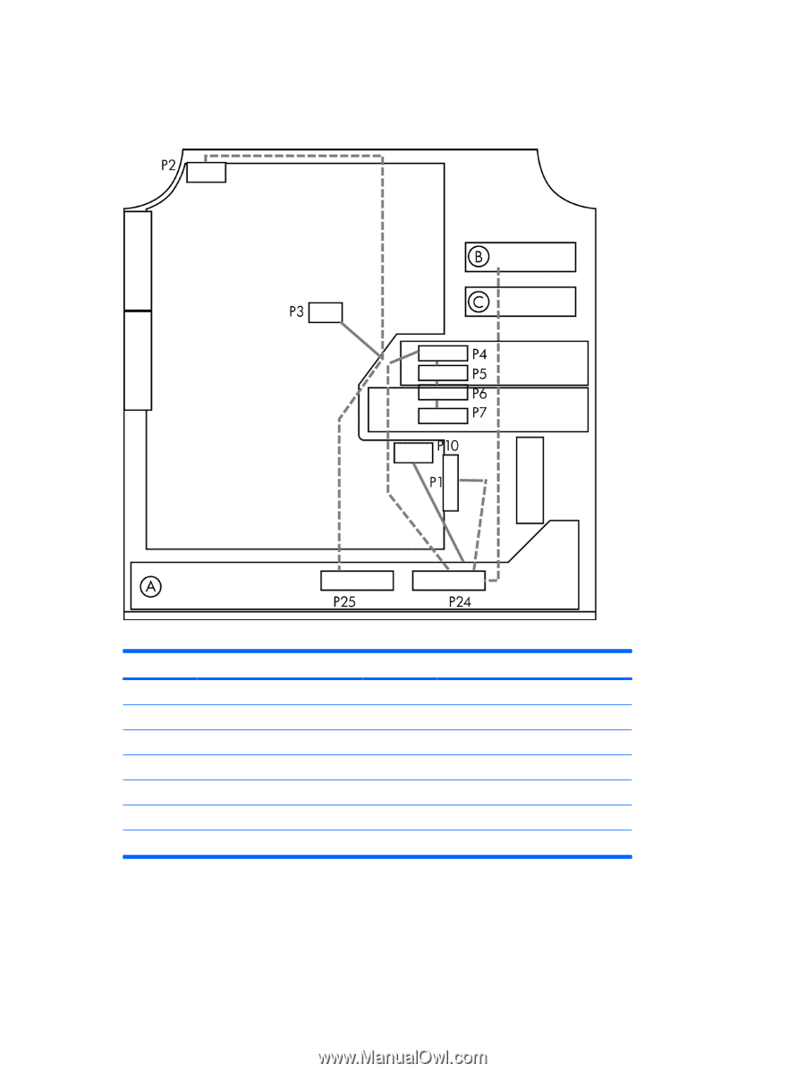
For help with identifying power cables, see the following figure and table. Ensure that all cables are
routed or tied so they cannot interfere with the processor heatsink fans.
Figure 5-10
Power connector identification for a typical configuration
Table 5-4
Power connector description
Item
Description
Item
Description
P1
Main power
P10
Graphics power
P2
Memory power
P24
Power to main and drives
P3
Memory power
P25
Power to CPU and memory
P4
SATA power
A
Power supply
P5
SATA power
B
HDD bay 0
P6
IDE power
C
HDD bay 1
P7
FDD power
82
Chapter 5
Replacing components
ENWW