HP Z600 HP Z600 Workstation Maintenance and Service Guide - Page 140
CAUTION, Seating the DIMM
 |
UPC - 884962074053
View all HP Z600 manuals
Add to My Manuals
Save this manual to your list of manuals |
Page 140 highlights
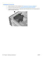
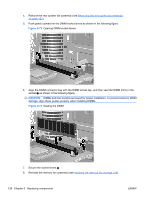
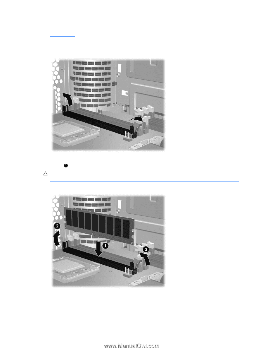
4. Remove the rear system fan assembly (see Removing the rear system fan assembly on page 122). 5. Push gently outward on the DIMM socket levers as shown in the following figure. Figure 5-73 Opening DIMM socket levers 6. Align the DIMM connector key with the DIMM socket key, and then seat the DIMM firmly in the socket as shown in the following figure. CAUTION: DIMMs and their sockets are keyed for proper installation. To prevent socket or DIMM damage, align these guides properly when installing DIMMs. Figure 5-74 Seating the DIMM 7. Secure the socket levers 2. 8. Reinstall the memory fan assembly (see Installing the memory fan on page 124). 128 Chapter 5 Replacing components ENWW
-
 1
1 -
2
-
3
-
4
-
5
-
6
-
7
-
8
-
9
-
10
-
11
-
12
-
13
-
14
-
15
-
16
-
17
-
18
-
19
-
20
-
21
-
22
-
23
-
24
-
25
-
26
-
27
-
28
-
29
-
30
-
31
-
32
-
33
-
34
-
35
-
36
-
37
-
38
-
39
-
40
-
41
-
42
-
43
-
44
-
45
-
46
-
47
-
48
-
49
-
50
-
51
-
52
-
53
-
54
-
55
-
56
-
57
-
58
-
59
-
60
-
61
-
62
-
63
-
64
-
65
-
66
-
67
-
68
-
69
-
70
-
71
-
72
-
73
-
74
-
75
-
76
-
77
-
78
-
79
-
80
-
81
-
82
-
83
-
84
-
85
-
86
-
87
-
88
-
89
-
90
-
91
-
92
-
93
-
94
-
95
-
96
-
97
-
98
-
99
-
100
-
101
-
102
-
103
-
104
-
105
-
106
-
107
-
108
-
109
-
110
-
111
-
112
-
113
-
114
-
115
-
116
-
117
-
118
-
119
-
120
-
121
-
122
-
123
-
124
-
125
-
126
-
127
-
128
-
129
-
130
-
131
-
132
-
133
-
134
-
 135
135 -
 136
136 -
 137
137 -
 138
138 -
 139
139 -
 140
140 -
 141
141 -
 142
142 -
 143
143 -
 144
144 -
 145
145 -
146
-
147
-
148
-
149
-
150
-
151
-
152
-
153
-
154
-
155
-
156
-
157
-
158
-
159
-
160
-
161
-
162
-
163
-
164
-
165
-
166
-
167
-
168
-
169
-
170
-
171
-
172
-
173
-
174
-
175
-
176
-
177
-
178
-
179
-
180
-
181
-
182
-
183
-
184
-
185
-
186
-
187
-
188
-
189
-
190
-
191
-
192
-
193
-
194
-
195
-
196
-
197
-
198
-
199
-
200
-
201
-
202
-
203
-
204
-
205
-
206
-
207
-
208
-
209
-
210
-
211
-
212
-
213
-
214
-
215
-
216
-
217
-
218
-
219
-
220
-
221
-
222
-
223
-
224
-
225
-
226
-
227
-
228
-
229
-
230
-
231
-
232
-
233
-
234
-
235
-
236
-
237
 |
 |
4.
Remove the rear system fan assembly (see
Removing the rear system fan assembly
on page
122
).
5.
Push gently outward on the DIMM socket levers as shown in the following figure.
Figure 5-73
Opening DIMM socket levers
6.
Align the DIMM connector key with the DIMM socket key, and then seat the DIMM firmly in the
socket
as shown in the following figure.
CAUTION:
DIMMs and their sockets are keyed for proper installation. To prevent socket or DIMM
damage, align these guides properly when installing DIMMs.
Figure 5-74
Seating the DIMM
7.
Secure the socket levers
2
.
8.
Reinstall the memory fan assembly (see
Installing the memory fan
on page
124
).
128
Chapter 5
Replacing components
ENWW