HP Z600 HP Z600 Workstation Maintenance and Service Guide - Page 142
Expansion card slot identification
 |
UPC - 884962074053
View all HP Z600 manuals
Add to My Manuals
Save this manual to your list of manuals |
Page 142 highlights
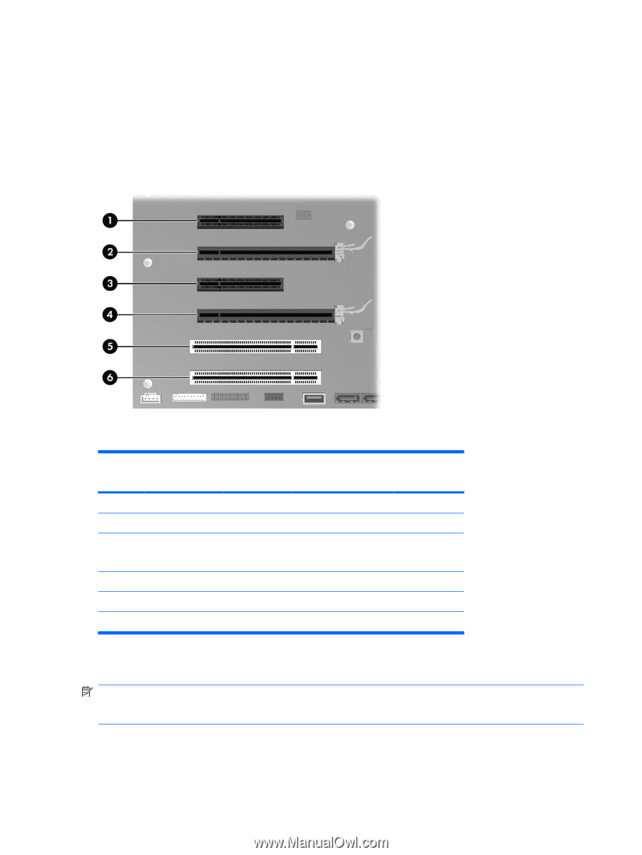
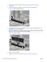
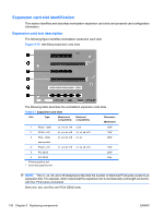
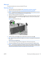
Expansion card slot identification This section identifies and describes workstation expansion card slots and presents card configuration information. Expansion card slot description The following figure identifies workstation expansion card slots. Figure 5-75 Identifying expansion card slots The following table describes the workstation expansion card slots. Table 5-7 Expansion card slots Slot Type Mechanical Electrical compatibility compatibility Slot power (Maximum) 1 PCIe2 - x8(4) 21 PCIe2 - x16 x1, x4, x8, x16 x1,x4 x1, x4, x8, x16 x1, x4, x8, x16 25W 75W 3 PCIe - x8(4) open-ended 42 PCIe2 - x16 x1, x4, x8, x16 x1, x4 x1, x4, x8, x16 x1, x4, x8, x16 25W 75W 5 PCI 32/33 25W 6 PCI 32/33 1 Primary graphics slot 2 Secondary graphics slot 25W NOTE: The x1, x4, x8, and x16 designators describe the number of electrical PCIe lanes routed to an expansion slot. For example, x8(4) means that the expansion slot is mechanically a x8 length connector, with four PCIe lanes connected. Slots one, two, and four are PCIe GEN2 slots. 130 Chapter 5 Replacing components ENWW
-
 1
1 -
2
-
3
-
4
-
5
-
6
-
7
-
8
-
9
-
10
-
11
-
12
-
13
-
14
-
15
-
16
-
17
-
18
-
19
-
20
-
21
-
22
-
23
-
24
-
25
-
26
-
27
-
28
-
29
-
30
-
31
-
32
-
33
-
34
-
35
-
36
-
37
-
38
-
39
-
40
-
41
-
42
-
43
-
44
-
45
-
46
-
47
-
48
-
49
-
50
-
51
-
52
-
53
-
54
-
55
-
56
-
57
-
58
-
59
-
60
-
61
-
62
-
63
-
64
-
65
-
66
-
67
-
68
-
69
-
70
-
71
-
72
-
73
-
74
-
75
-
76
-
77
-
78
-
79
-
80
-
81
-
82
-
83
-
84
-
85
-
86
-
87
-
88
-
89
-
90
-
91
-
92
-
93
-
94
-
95
-
96
-
97
-
98
-
99
-
100
-
101
-
102
-
103
-
104
-
105
-
106
-
107
-
108
-
109
-
110
-
111
-
112
-
113
-
114
-
115
-
116
-
117
-
118
-
119
-
120
-
121
-
122
-
123
-
124
-
125
-
126
-
127
-
128
-
129
-
130
-
131
-
132
-
133
-
134
-
135
-
136
-
 137
137 -
 138
138 -
 139
139 -
 140
140 -
 141
141 -
 142
142 -
 143
143 -
 144
144 -
 145
145 -
 146
146 -
 147
147 -
148
-
149
-
150
-
151
-
152
-
153
-
154
-
155
-
156
-
157
-
158
-
159
-
160
-
161
-
162
-
163
-
164
-
165
-
166
-
167
-
168
-
169
-
170
-
171
-
172
-
173
-
174
-
175
-
176
-
177
-
178
-
179
-
180
-
181
-
182
-
183
-
184
-
185
-
186
-
187
-
188
-
189
-
190
-
191
-
192
-
193
-
194
-
195
-
196
-
197
-
198
-
199
-
200
-
201
-
202
-
203
-
204
-
205
-
206
-
207
-
208
-
209
-
210
-
211
-
212
-
213
-
214
-
215
-
216
-
217
-
218
-
219
-
220
-
221
-
222
-
223
-
224
-
225
-
226
-
227
-
228
-
229
-
230
-
231
-
232
-
233
-
234
-
235
-
236
-
237
 |
 |