HP xw3400 HP xw3400 Workstation - Service and Technical Reference Guide - Page 95
Front I/O panel housing assembly, system board.
 |
View all HP xw3400 manuals
Add to My Manuals
Save this manual to your list of manuals |
Page 95 highlights
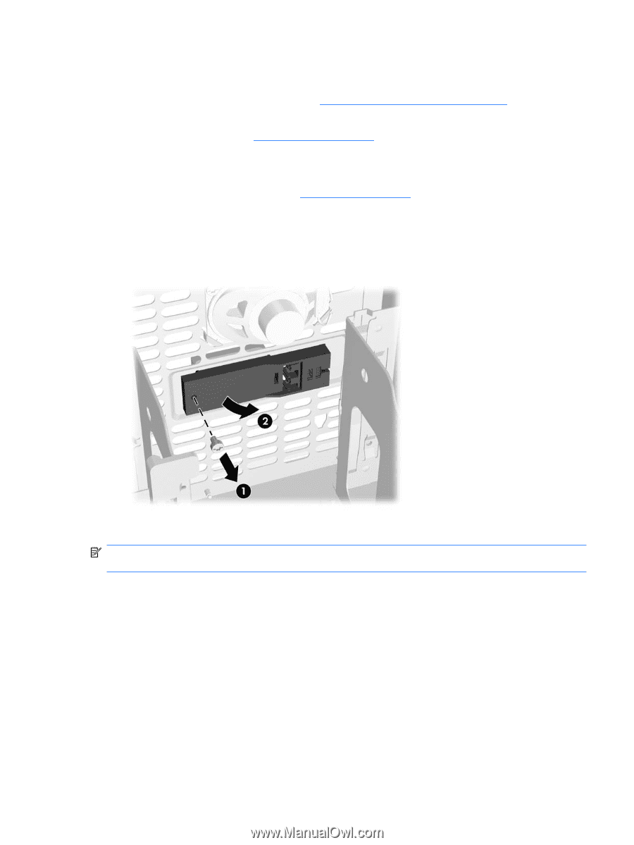
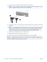
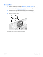
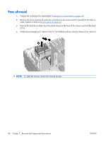
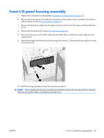
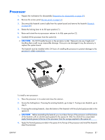
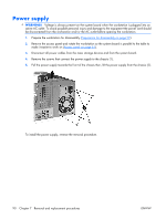
Front I/O panel housing assembly 1. Prepare the workstation for disassembly (Preparation for disassembly on page 59). 2. Remove the access panel and rotate the workstation so the system board is parallel to the table to make it easier to work on (Access panel on page 61). 3. Remove the hard drive cables from the plastic shroud at the front of the chassis and from the hard drives. 4. Remove the shroud from the chassis (Fan shroud on page 84). 5. Disconnect the power switch/LED cable, the front USB cable, and the front audio cable from the system board. 6. Remove the single screw that secure the housing to the chassis (1), then push the housing to the inside of the chassis (2). To install the housing assembly, reverse the removal procedures. NOTE: When installing the housing, insert the power-button end into the opening and then rotate the USB end into position before inserting the retaining screw. ENWW Front I/O panel housing assembly 85
-
 1
1 -
2
-
3
-
4
-
5
-
6
-
7
-
8
-
9
-
10
-
11
-
12
-
13
-
14
-
15
-
16
-
17
-
18
-
19
-
20
-
21
-
22
-
23
-
24
-
25
-
26
-
27
-
28
-
29
-
30
-
31
-
32
-
33
-
34
-
35
-
36
-
37
-
38
-
39
-
40
-
41
-
42
-
43
-
44
-
45
-
46
-
47
-
48
-
49
-
50
-
51
-
52
-
53
-
54
-
55
-
56
-
57
-
58
-
59
-
60
-
61
-
62
-
63
-
64
-
65
-
66
-
67
-
68
-
69
-
70
-
71
-
72
-
73
-
74
-
75
-
76
-
77
-
78
-
79
-
80
-
81
-
82
-
83
-
84
-
85
-
86
-
87
-
88
-
89
-
 90
90 -
 91
91 -
 92
92 -
 93
93 -
 94
94 -
 95
95 -
 96
96 -
 97
97 -
 98
98 -
 99
99 -
 100
100 -
101
-
102
-
103
-
104
-
105
-
106
-
107
-
108
-
109
-
110
-
111
-
112
-
113
-
114
-
115
-
116
-
117
-
118
-
119
-
120
-
121
-
122
-
123
-
124
-
125
-
126
-
127
-
128
-
129
-
130
-
131
-
132
-
133
-
134
-
135
-
136
-
137
-
138
-
139
-
140
-
141
-
142
-
143
-
144
-
145
-
146
-
147
-
148
-
149
-
150
-
151
-
152
-
153
-
154
-
155
-
156
-
157
-
158
-
159
-
160
-
161
-
162
-
163
-
164
-
165
-
166
-
167
-
168
-
169
-
170
-
171
-
172
-
173
-
174
-
175
-
176
-
177
-
178
-
179
-
180
-
181
-
182
 |
 |