Icom IC-9100 Instruction Manual - Page 32
Antenna connection
 |
View all Icom IC-9100 manuals
Add to My Manuals
Save this manual to your list of manuals |
Page 32 highlights
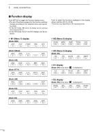
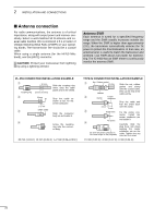
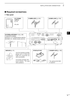
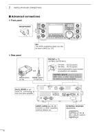
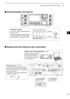
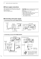
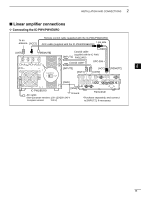
2 INSTALLATION AND CONNECTIONS ■ Antenna connection For radio communications, the antenna is of critical importance, along with output power and receiver sensitivity. Select a well-matched 50 ø antenna and coaxial cable feedline. We recommend 1.5:1 or better of Voltage Standing Wave Ratio (VSWR) on your operating bands. The transmission line should be a coaxial cable. When using a single antenna (for the HF/50 MHz band), use the [ANT1] connector. CAUTION: Protect your transceiver from lightning by using a lightning arrestor. Antenna SWR Each antenna is tuned for a specified frequency range and the SWR usually increases outside the range. When the SWR is higher than approximately 2.0:1, the transceiver automatically reduces the TX power to protect the final transistors. In that case, an antenna tuner is useful to match the transceiver and antenna. Low SWR allows full power for transmitting. The IC-9100 has an SWR meter to continuously monitor the antenna SWR. PL-259 CONNECTOR INSTALLATION EXAMPLE q 30 mm Coupling ring 10 mm (tin here) Slide the coupling ring down. Strip the cable jacket and tin the shield. w 10 mm tin Strip the cable as shown at left. Tin the center conductor. 1-2 mm e solder solder Slide the connector body on and solder it. r Screw the coupling ring onto the connector body. 30 mm (1.18 in) 10 mm (0.39 in) 1-2 mm (0.04-0.08 in) TYPE-N CONNECTOR INSTALLATION EXAMPLE q Nut Rubber gasket 15 mm Slide the nut, rubber gasket and clamp over the coaxial cable, Washer then cut the end of the cable evenly. w Clamp Center conductor 3 mm 6 mm Strip the cable and fold the braid back over the clamp. e Solder hole Tin the center con- ductor. Install the center conductor pin No space and solder it. r Carefully slide the plug body into place aligning the center conductor pin on the Be sure the center conductor is the same height as the plug body. cable. Tighten the nut onto the plug body. 15 mm (0.59 in) 3 mm (0.12 in) 6 mm (0.24 in) 23
-
 1
1 -
2
-
3
-
4
-
5
-
6
-
7
-
8
-
9
-
10
-
11
-
12
-
13
-
14
-
15
-
16
-
17
-
18
-
19
-
20
-
21
-
22
-
23
-
24
-
25
-
26
-
 27
27 -
 28
28 -
 29
29 -
 30
30 -
 31
31 -
 32
32 -
 33
33 -
 34
34 -
 35
35 -
 36
36 -
 37
37 -
38
-
39
-
40
-
41
-
42
-
43
-
44
-
45
-
46
-
47
-
48
-
49
-
50
-
51
-
52
-
53
-
54
-
55
-
56
-
57
-
58
-
59
-
60
-
61
-
62
-
63
-
64
-
65
-
66
-
67
-
68
-
69
-
70
-
71
-
72
-
73
-
74
-
75
-
76
-
77
-
78
-
79
-
80
-
81
-
82
-
83
-
84
-
85
-
86
-
87
-
88
-
89
-
90
-
91
-
92
-
93
-
94
-
95
-
96
-
97
-
98
-
99
-
100
-
101
-
102
-
103
-
104
-
105
-
106
-
107
-
108
-
109
-
110
-
111
-
112
-
113
-
114
-
115
-
116
-
117
-
118
-
119
-
120
-
121
-
122
-
123
-
124
-
125
-
126
-
127
-
128
-
129
-
130
-
131
-
132
-
133
-
134
-
135
-
136
-
137
-
138
-
139
-
140
-
141
-
142
-
143
-
144
-
145
-
146
-
147
-
148
-
149
-
150
-
151
-
152
-
153
-
154
-
155
-
156
-
157
-
158
-
159
-
160
-
161
-
162
-
163
-
164
-
165
-
166
-
167
-
168
-
169
-
170
-
171
-
172
-
173
-
174
-
175
-
176
-
177
-
178
-
179
-
180
-
181
-
182
-
183
-
184
-
185
-
186
-
187
-
188
-
189
-
190
-
191
-
192
-
193
-
194
-
195
-
196
-
197
-
198
-
199
-
200
-
201
-
202
-
203
-
204
-
205
-
206
-
207
-
208
-
209
-
210
-
211
-
212
 |
 |