Intel SR2400SYSD2 User Guide - Page 29
Hot-Swap SATA Backplane Connections, Rear of SATA Backplane
 |
UPC - 735858169172
View all Intel SR2400SYSD2 manuals
Add to My Manuals
Save this manual to your list of manuals |
Page 29 highlights
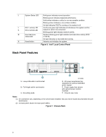
Server Chassis Features Hot-Swap SATA Backplane Connections The diagram below shows the connection points on the rear of the SATA backplane. The power supply, server board and a SATA RAID card can be connected to the locations below. EF A B C D GH I J A. OPT connector F. SATA channel B connector B. Location for sixth drive board (accessory) G. SATA channel C connector C. Fan distribution cable connector H. SATA channel A connector D. Flex cable connector I. Backplane power connector E. SATA channel D connector J. SATA channel E connector Figure 3. Rear of SATA Backplane TP01363 Hot-Swap SCSI Backplane Connections The diagram below shows the connection points on the rear of the SCSI backplane. The power supply, server board and a SCSI RAID card can be connected to the locations below. A B C D E F A. SCSI connector D. Fan distribution cable connector B. OPT connector E. Flex cable connector C. Location for sixth drive board (accessory) F. Backplane power connector Figure 4. Rear of SCSI Backplane TP01364 Intel® Server Chassis SR2400/SR2400DC User Guide 5
-
 1
1 -
2
-
3
-
4
-
5
-
6
-
7
-
8
-
9
-
10
-
11
-
12
-
13
-
14
-
15
-
16
-
17
-
18
-
19
-
20
-
21
-
22
-
23
-
 24
24 -
 25
25 -
 26
26 -
 27
27 -
 28
28 -
 29
29 -
 30
30 -
 31
31 -
 32
32 -
 33
33 -
 34
34 -
35
-
36
-
37
-
38
-
39
-
40
-
41
-
42
-
43
-
44
-
45
-
46
-
47
-
48
-
49
-
50
-
51
-
52
-
53
-
54
-
55
-
56
-
57
-
58
-
59
-
60
-
61
-
62
-
63
-
64
-
65
-
66
-
67
-
68
-
69
-
70
-
71
-
72
-
73
-
74
-
75
-
76
-
77
-
78
-
79
-
80
-
81
-
82
-
83
-
84
-
85
-
86
-
87
-
88
-
89
-
90
-
91
-
92
-
93
-
94
-
95
-
96
-
97
-
98
-
99
-
100
-
101
-
102
-
103
-
104
-
105
-
106
-
107
-
108
-
109
-
110
-
111
-
112
-
113
-
114
-
115
-
116
-
117
-
118
-
119
-
120
-
121
-
122
-
123
-
124
-
125
-
126
-
127
-
128
-
129
-
130
-
131
-
132
-
133
-
134
-
135
-
136
-
137
-
138
-
139
 |
 |
