Intel SR2400SYSD2 User Guide - Page 31
Intel® Local Control Panel
 |
UPC - 735858169172
View all Intel SR2400SYSD2 manuals
Add to My Manuals
Save this manual to your list of manuals |
Page 31 highlights
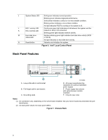
Server Chassis Features Intel® Local Control Panel The diagram below shows the features available on the Intel® Local Control Panel. The Intel Local Control Panel is one of two required control options that can be selected. The other option is the Standard Control Panel. For instructions on installing the Standard Control Panel, see "Replacing the Control Panel". ✏ NOTE This control panel requires the installation of the Intel® Management Module, Professional Edition or Advance Edition. Some server boards do not support this control panel. See your server board documentation to determine if this control panel is compatible with your server board. A B C D E F N ML KJ I H G TP00780 Callout A B C D E F G Feature USB 2.0 ports LCD display Menu control button, scroll up Menu control button, scroll down Menu control button, scroll left Menu control button, scroll right System Identification LED H Power/Sleep LED I Power/Sleep button Function Allows you to attach a USB component to the front of the chassis. Screen on which system information is displayed. Scroll up one option at a time. Scroll down one option at a time. Move to the previous option. Move to the previous page. Solid blue indicates system identification is active. No light indicates system identification is not activated. Continuous green light indicates the system has power applied to it. Blinking green indicates the system is in S1 sleep state. No light indicates the power is off / is in ACPI S4 or S5 state. Toggles the system power on/off. Sleep button for ACPI-compatible operating systems. Continued Intel® Server Chassis SR2400/SR2400DC User Guide 7
-
 1
1 -
2
-
3
-
4
-
5
-
6
-
7
-
8
-
9
-
10
-
11
-
12
-
13
-
14
-
15
-
16
-
17
-
18
-
19
-
20
-
21
-
22
-
23
-
24
-
25
-
 26
26 -
 27
27 -
 28
28 -
 29
29 -
 30
30 -
 31
31 -
 32
32 -
 33
33 -
 34
34 -
 35
35 -
 36
36 -
37
-
38
-
39
-
40
-
41
-
42
-
43
-
44
-
45
-
46
-
47
-
48
-
49
-
50
-
51
-
52
-
53
-
54
-
55
-
56
-
57
-
58
-
59
-
60
-
61
-
62
-
63
-
64
-
65
-
66
-
67
-
68
-
69
-
70
-
71
-
72
-
73
-
74
-
75
-
76
-
77
-
78
-
79
-
80
-
81
-
82
-
83
-
84
-
85
-
86
-
87
-
88
-
89
-
90
-
91
-
92
-
93
-
94
-
95
-
96
-
97
-
98
-
99
-
100
-
101
-
102
-
103
-
104
-
105
-
106
-
107
-
108
-
109
-
110
-
111
-
112
-
113
-
114
-
115
-
116
-
117
-
118
-
119
-
120
-
121
-
122
-
123
-
124
-
125
-
126
-
127
-
128
-
129
-
130
-
131
-
132
-
133
-
134
-
135
-
136
-
137
-
138
-
139
 |
 |
