Intel SR2400SYSD2 User Guide - Page 32
Back Panel Features, Intel, Local Control Panel, Chassis Back
 |
UPC - 735858169172
View all Intel SR2400SYSD2 manuals
Add to My Manuals
Save this manual to your list of manuals |
Page 32 highlights
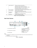
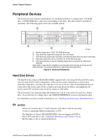
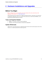
J System Status LED Solid green indicates normal operation. Blinking green indicates degraded performance. Solid amber indicates a critical or non-recoverable condition. Blinking amber indicates a non-critical condition. No light indicates POST is running or the system is off. L NIC 1 activity LED Continuous green light indicates a link between the system and the K NIC 2 activity LED network to which it is connected. Blinking green light indicates network activity. M Hard disk drive status LED Random blinking green light indicates hard disk drive activity (SCSI or SATA). No light indicates no hard disk drive activity. N Reset button Reboots and initializes the system. Figure 6. Intel® Local Control Panel Back Panel Features A B C D F A. Low-profile add-in card bracket B. Full-height add-in card bracket C. Grounding studs E AF00638 D. AC power receptacles (top receptacle for optional redundant power supply) E. Power supply fans (shown with optional power module installed) F. I/O ports (see note) Notes: (1) I/O connectors vary, depending on the server board installed. See your server board documentation for port identification. (2) AC back panel shown; DC back panel differs. Figure 7. Chassis Back 8
-
 1
1 -
2
-
3
-
4
-
5
-
6
-
7
-
8
-
9
-
10
-
11
-
12
-
13
-
14
-
15
-
16
-
17
-
18
-
19
-
20
-
21
-
22
-
23
-
24
-
25
-
26
-
 27
27 -
 28
28 -
 29
29 -
 30
30 -
 31
31 -
 32
32 -
 33
33 -
 34
34 -
 35
35 -
 36
36 -
 37
37 -
38
-
39
-
40
-
41
-
42
-
43
-
44
-
45
-
46
-
47
-
48
-
49
-
50
-
51
-
52
-
53
-
54
-
55
-
56
-
57
-
58
-
59
-
60
-
61
-
62
-
63
-
64
-
65
-
66
-
67
-
68
-
69
-
70
-
71
-
72
-
73
-
74
-
75
-
76
-
77
-
78
-
79
-
80
-
81
-
82
-
83
-
84
-
85
-
86
-
87
-
88
-
89
-
90
-
91
-
92
-
93
-
94
-
95
-
96
-
97
-
98
-
99
-
100
-
101
-
102
-
103
-
104
-
105
-
106
-
107
-
108
-
109
-
110
-
111
-
112
-
113
-
114
-
115
-
116
-
117
-
118
-
119
-
120
-
121
-
122
-
123
-
124
-
125
-
126
-
127
-
128
-
129
-
130
-
131
-
132
-
133
-
134
-
135
-
136
-
137
-
138
-
139
 |
 |
