Netgear GS752TP GS728TP/GS728TPP/GS752TP Software Administration Manual - Page 257
Sample Standard IP ACL Configuration, Destination MAC Mask, Source MAC, Source MAC Mask, VLAN ID
 |
View all Netgear GS752TP manuals
Add to My Manuals
Save this manual to your list of manuals |
Page 257 highlights
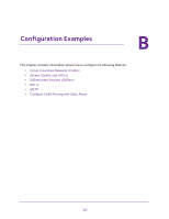
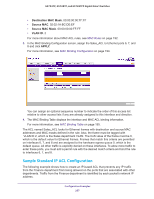
GS752TP, GS728TP, and GS728TPP Gigabit Smart Switches • Destination MAC Mask. 00:00:00:00:FF:FF • Source MAC. 02:02:1A:BC:DE:EF • Source MAC Mask. 00:00:00:00:FF:FF • VLAN ID. 2 For more information about MAC ACL rules, see MAC Rules on page 192. 3. In the MAC Binding Configuration screen, assign the Sales_ACL to Ethernet ports 6, 7, and 8 and click APPLY. For more information, see MAC Binding Configuration on page 194. You can assign an optional sequence number to indicate the order of this access list relative to other access lists if any are already assigned to this interface and direction. 4. The MAC Binding Table displays the interface and MAC ACL binding information. For more information, see MAC Binding Table on page 195. The ACL named Sales_ACL looks for Ethernet frames with destination and source MAC addresses and MAC masks defined in the rule. Also, the frame must be tagged with VLAN ID 2, which is the Sales department VLAN. The CoS value of the frame must be 0, which is the default value for Ethernet frames. Frames that match this criteria are permitted on interfaces 6, 7, and 8 and are assigned to the hardware egress queue 0, which is the default queue. All other traffic is explicitly denied on these interfaces. To allow more traffic to enter these ports, you must add a permit rule with the desired match criteria and bind the rule to interfaces 6, 7, and 8. Sample Standard IP ACL Configuration The following example shows how to create an IP-based ACL that prevents any IP traffic from the Finance department from being allowed on the ports that are associated with other departments. Traffic from the Finance department is identified by each packet's network IP address. Configuration Examples 257
-
 1
1 -
2
-
3
-
4
-
5
-
6
-
7
-
8
-
9
-
10
-
11
-
12
-
13
-
14
-
15
-
16
-
17
-
18
-
19
-
20
-
21
-
22
-
23
-
24
-
25
-
26
-
27
-
28
-
29
-
30
-
31
-
32
-
33
-
34
-
35
-
36
-
37
-
38
-
39
-
40
-
41
-
42
-
43
-
44
-
45
-
46
-
47
-
48
-
49
-
50
-
51
-
52
-
53
-
54
-
55
-
56
-
57
-
58
-
59
-
60
-
61
-
62
-
63
-
64
-
65
-
66
-
67
-
68
-
69
-
70
-
71
-
72
-
73
-
74
-
75
-
76
-
77
-
78
-
79
-
80
-
81
-
82
-
83
-
84
-
85
-
86
-
87
-
88
-
89
-
90
-
91
-
92
-
93
-
94
-
95
-
96
-
97
-
98
-
99
-
100
-
101
-
102
-
103
-
104
-
105
-
106
-
107
-
108
-
109
-
110
-
111
-
112
-
113
-
114
-
115
-
116
-
117
-
118
-
119
-
120
-
121
-
122
-
123
-
124
-
125
-
126
-
127
-
128
-
129
-
130
-
131
-
132
-
133
-
134
-
135
-
136
-
137
-
138
-
139
-
140
-
141
-
142
-
143
-
144
-
145
-
146
-
147
-
148
-
149
-
150
-
151
-
152
-
153
-
154
-
155
-
156
-
157
-
158
-
159
-
160
-
161
-
162
-
163
-
164
-
165
-
166
-
167
-
168
-
169
-
170
-
171
-
172
-
173
-
174
-
175
-
176
-
177
-
178
-
179
-
180
-
181
-
182
-
183
-
184
-
185
-
186
-
187
-
188
-
189
-
190
-
191
-
192
-
193
-
194
-
195
-
196
-
197
-
198
-
199
-
200
-
201
-
202
-
203
-
204
-
205
-
206
-
207
-
208
-
209
-
210
-
211
-
212
-
213
-
214
-
215
-
216
-
217
-
218
-
219
-
220
-
221
-
222
-
223
-
224
-
225
-
226
-
227
-
228
-
229
-
230
-
231
-
232
-
233
-
234
-
235
-
236
-
237
-
238
-
239
-
240
-
241
-
242
-
243
-
244
-
245
-
246
-
247
-
248
-
249
-
250
-
251
-
 252
252 -
 253
253 -
 254
254 -
 255
255 -
 256
256 -
 257
257 -
 258
258 -
 259
259 -
 260
260 -
 261
261 -
 262
262 -
263
-
264
-
265
-
266
-
267
-
268
-
269
-
270
-
271
-
272
-
273
-
274
-
275
 |
 |