Netgear GS752TP GS728TP/GS728TPP/GS752TP Software Administration Manual - Page 258
Rule ID, Action, Match Every, Source IP Address, Source IP Mask, APPLY, In the IP ACL screen
 |
View all Netgear GS752TP manuals
Add to My Manuals
Save this manual to your list of manuals |
Page 258 highlights
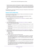
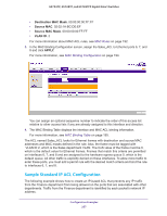
GS752TP, GS728TP, and GS728TPP Gigabit Smart Switches 1. In the IP ACL screen, create an IP ACL with an IP ACL ID of 1. For more information, see IP ACL on page 196. 2. In the IP Rules screen, create a rule for IP ACL 1 with the following settings: • Rule ID. 1 • Action. Deny • Match Every. False • Source IP Address. 192.168.187.0 • Source IP Mask. 255.255.255.0 For more information about IP ACL rules, see IP Rules on page 198. 3. Click Add. 4. In the IP Rules screen, create a second rule for IP ACL 1 with the following settings: • Rule ID. 2 • Action. Permit • Match Every. True 5. Click Add. 6. In the IP Binding Configuration screen, assign ACL ID 1 to the Ethernet ports 2, 3, and 4, and assign a sequence number of 1. For more information, see IP Binding Configuration on page 205. By default, this IP ACL is bound on the inbound direction, so it examines traffic as it enters the switch. 7. Click APPLY. 8. Use the IP Binding Table screen to view the interfaces and IP ACL binding information. For more information, see IP Binding Table on page 206. The IP ACL in this example matches all packets with the source IP address and subnet mask of the Finance department network and denies it on the Ethernet interfaces 2, 3, and 4 of the switch. The second rule permits all non-Finance traffic on the ports. The second rule is required because there is an explicit deny all rule as the lowest priority rule. Configuration Examples 258
-
 1
1 -
2
-
3
-
4
-
5
-
6
-
7
-
8
-
9
-
10
-
11
-
12
-
13
-
14
-
15
-
16
-
17
-
18
-
19
-
20
-
21
-
22
-
23
-
24
-
25
-
26
-
27
-
28
-
29
-
30
-
31
-
32
-
33
-
34
-
35
-
36
-
37
-
38
-
39
-
40
-
41
-
42
-
43
-
44
-
45
-
46
-
47
-
48
-
49
-
50
-
51
-
52
-
53
-
54
-
55
-
56
-
57
-
58
-
59
-
60
-
61
-
62
-
63
-
64
-
65
-
66
-
67
-
68
-
69
-
70
-
71
-
72
-
73
-
74
-
75
-
76
-
77
-
78
-
79
-
80
-
81
-
82
-
83
-
84
-
85
-
86
-
87
-
88
-
89
-
90
-
91
-
92
-
93
-
94
-
95
-
96
-
97
-
98
-
99
-
100
-
101
-
102
-
103
-
104
-
105
-
106
-
107
-
108
-
109
-
110
-
111
-
112
-
113
-
114
-
115
-
116
-
117
-
118
-
119
-
120
-
121
-
122
-
123
-
124
-
125
-
126
-
127
-
128
-
129
-
130
-
131
-
132
-
133
-
134
-
135
-
136
-
137
-
138
-
139
-
140
-
141
-
142
-
143
-
144
-
145
-
146
-
147
-
148
-
149
-
150
-
151
-
152
-
153
-
154
-
155
-
156
-
157
-
158
-
159
-
160
-
161
-
162
-
163
-
164
-
165
-
166
-
167
-
168
-
169
-
170
-
171
-
172
-
173
-
174
-
175
-
176
-
177
-
178
-
179
-
180
-
181
-
182
-
183
-
184
-
185
-
186
-
187
-
188
-
189
-
190
-
191
-
192
-
193
-
194
-
195
-
196
-
197
-
198
-
199
-
200
-
201
-
202
-
203
-
204
-
205
-
206
-
207
-
208
-
209
-
210
-
211
-
212
-
213
-
214
-
215
-
216
-
217
-
218
-
219
-
220
-
221
-
222
-
223
-
224
-
225
-
226
-
227
-
228
-
229
-
230
-
231
-
232
-
233
-
234
-
235
-
236
-
237
-
238
-
239
-
240
-
241
-
242
-
243
-
244
-
245
-
246
-
247
-
248
-
249
-
250
-
251
-
252
-
 253
253 -
 254
254 -
 255
255 -
 256
256 -
 257
257 -
 258
258 -
 259
259 -
 260
260 -
 261
261 -
 262
262 -
 263
263 -
264
-
265
-
266
-
267
-
268
-
269
-
270
-
271
-
272
-
273
-
274
-
275
 |
 |