Netgear GS752TP GS728TP/GS728TPP/GS752TP Software Administration Manual - Page 92
Spanning Tree Protocol, Enable, Disable, APPLY
 |
View all Netgear GS752TP manuals
Add to My Manuals
Save this manual to your list of manuals |
Page 92 highlights
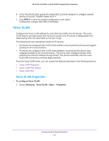
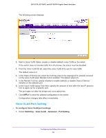
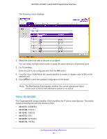
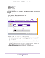
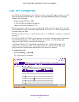
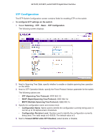
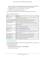
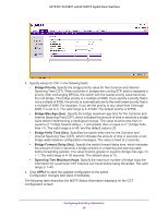
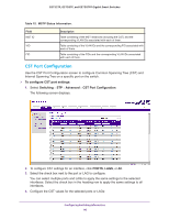
GS752TP, GS728TP, and GS728TPP Gigabit Smart Switches 2. To configure Auto-VoIP interface settings for a physical port or a LAG port, click PORT, LAGS, or ALL. 3. Enter the interface name in the Go To Interface field and click the Go button. The entry corresponding to the specified port is selected. 4. Select Enable or Disable from the Auto-VoIP Mode drop-down list, as the Auto-VoIP administrative mode for the interface. 5. Click APPLY to send the updated configuration to the switch. Spanning Tree Protocol The Spanning Tree Protocol (STP) provides a tree topology for any arrangement of bridges. STP also provides one path between end stations on a network, eliminating loops. Spanning tree versions supported include Common STP, Multiple STP, and Rapid STP. Classic STP provides a single path between end stations, avoiding and eliminating loops. For information about configuring Common STP, see CST Port Configuration on page 96. Multiple Spanning Tree Protocol (MSTP) supports multiple instances of spanning tree to efficiently channel VLAN traffic over different interfaces. Each instance of the spanning tree behaves in the manner specified in IEEE 802.1w, Rapid Spanning Tree (RSTP), with slight modifications in the working but not the end effect (chief among the effects, is the rapid transitioning of the port to 'forwarding'). The difference between the RSTP and the traditional STP (IEEE 802.1D) is the ability to configure and recognize full-duplex connectivity and ports that are connected to end stations, resulting in rapid transitioning of the port to forwarding state and the suppression of Topology Change Notification. These features are represented by the parameters point-to-point and edgeport. MSTP is compatible with both RSTP and STP, and can be configured to operate entirely as an RSTP bridge or an STP bridge. Note: For two bridges to be in the same region, the force version should be 802.1s, and their configuration name, digest key, and revision level should match. For more information about regions and their effect on network topology, refer to the IEEE 802.1Q standard. The STP link contains links to features described in the following sections: • STP Configuration • CST Configuration • CST Port Configuration • CST Port Status • Rapid STP • MST Configuration • MST Port Configuration Configuring Switching Information 92
-
 1
1 -
2
-
3
-
4
-
5
-
6
-
7
-
8
-
9
-
10
-
11
-
12
-
13
-
14
-
15
-
16
-
17
-
18
-
19
-
20
-
21
-
22
-
23
-
24
-
25
-
26
-
27
-
28
-
29
-
30
-
31
-
32
-
33
-
34
-
35
-
36
-
37
-
38
-
39
-
40
-
41
-
42
-
43
-
44
-
45
-
46
-
47
-
48
-
49
-
50
-
51
-
52
-
53
-
54
-
55
-
56
-
57
-
58
-
59
-
60
-
61
-
62
-
63
-
64
-
65
-
66
-
67
-
68
-
69
-
70
-
71
-
72
-
73
-
74
-
75
-
76
-
77
-
78
-
79
-
80
-
81
-
82
-
83
-
84
-
85
-
86
-
 87
87 -
 88
88 -
 89
89 -
 90
90 -
 91
91 -
 92
92 -
 93
93 -
 94
94 -
 95
95 -
 96
96 -
 97
97 -
98
-
99
-
100
-
101
-
102
-
103
-
104
-
105
-
106
-
107
-
108
-
109
-
110
-
111
-
112
-
113
-
114
-
115
-
116
-
117
-
118
-
119
-
120
-
121
-
122
-
123
-
124
-
125
-
126
-
127
-
128
-
129
-
130
-
131
-
132
-
133
-
134
-
135
-
136
-
137
-
138
-
139
-
140
-
141
-
142
-
143
-
144
-
145
-
146
-
147
-
148
-
149
-
150
-
151
-
152
-
153
-
154
-
155
-
156
-
157
-
158
-
159
-
160
-
161
-
162
-
163
-
164
-
165
-
166
-
167
-
168
-
169
-
170
-
171
-
172
-
173
-
174
-
175
-
176
-
177
-
178
-
179
-
180
-
181
-
182
-
183
-
184
-
185
-
186
-
187
-
188
-
189
-
190
-
191
-
192
-
193
-
194
-
195
-
196
-
197
-
198
-
199
-
200
-
201
-
202
-
203
-
204
-
205
-
206
-
207
-
208
-
209
-
210
-
211
-
212
-
213
-
214
-
215
-
216
-
217
-
218
-
219
-
220
-
221
-
222
-
223
-
224
-
225
-
226
-
227
-
228
-
229
-
230
-
231
-
232
-
233
-
234
-
235
-
236
-
237
-
238
-
239
-
240
-
241
-
242
-
243
-
244
-
245
-
246
-
247
-
248
-
249
-
250
-
251
-
252
-
253
-
254
-
255
-
256
-
257
-
258
-
259
-
260
-
261
-
262
-
263
-
264
-
265
-
266
-
267
-
268
-
269
-
270
-
271
-
272
-
273
-
274
-
275
 |
 |