Netgear GS752TP GS728TP/GS728TPP/GS752TP Software Administration Manual - Page 38
Green Ethernet Configuration, To con the Green Ethernet Configuration features
 |
View all Netgear GS752TP manuals
Add to My Manuals
Save this manual to your list of manuals |
Page 38 highlights
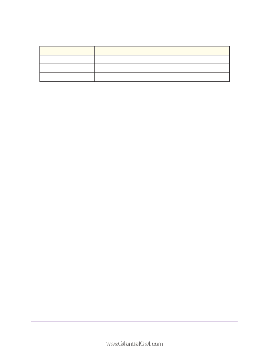
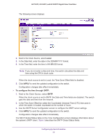
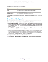
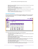
GS752TP, GS728TP, and GS728TPP Gigabit Smart Switches Table 7. Dynamic Host Configuration table fields Field Description Host Lists the host name you assign to the specified IP address. Type The type of the dynamic entry. IPv4/IPv6 Address Lists the IP address associated with the host name. Click CLEAR to delete dynamic host entries. The table repopulates with entries as they are learned. Green Ethernet Configuration The Green Ethernet features allow the switch to reduce power consumption on a per-port basis. Each switch can support one or more of the following features: • Auto Power Down Mode. When the Auto Power Down mode is enabled and the port link is down, the physical layer (PHY) automatically shuts down for a short period and wakes up to check link pulses. This mode reduces power consumption on the port when no link partner is present. • Short Cable Mode. With Short Cable mode enabled, the PHY goes into low-power mode when the cable length is less than a certain limit. • Energy Efficient Ethernet (EEE) Mode. EEE enables ports to enter a low-power mode to reduce power consumption during periods of low link utilization. EEE is defined by IEEE 802.3az. EEE enables both the send and receive sides of the link to disable some functionality for power savings when the link is lightly loaded. To configure the Green Ethernet Configuration features: 1. Select System Management Green Ethernet Green Ethernet Configuration. Configuring System Information 38
-
 1
1 -
2
-
3
-
4
-
5
-
6
-
7
-
8
-
9
-
10
-
11
-
12
-
13
-
14
-
15
-
16
-
17
-
18
-
19
-
20
-
21
-
22
-
23
-
24
-
25
-
26
-
27
-
28
-
29
-
30
-
31
-
32
-
 33
33 -
 34
34 -
 35
35 -
 36
36 -
 37
37 -
 38
38 -
 39
39 -
 40
40 -
 41
41 -
 42
42 -
 43
43 -
44
-
45
-
46
-
47
-
48
-
49
-
50
-
51
-
52
-
53
-
54
-
55
-
56
-
57
-
58
-
59
-
60
-
61
-
62
-
63
-
64
-
65
-
66
-
67
-
68
-
69
-
70
-
71
-
72
-
73
-
74
-
75
-
76
-
77
-
78
-
79
-
80
-
81
-
82
-
83
-
84
-
85
-
86
-
87
-
88
-
89
-
90
-
91
-
92
-
93
-
94
-
95
-
96
-
97
-
98
-
99
-
100
-
101
-
102
-
103
-
104
-
105
-
106
-
107
-
108
-
109
-
110
-
111
-
112
-
113
-
114
-
115
-
116
-
117
-
118
-
119
-
120
-
121
-
122
-
123
-
124
-
125
-
126
-
127
-
128
-
129
-
130
-
131
-
132
-
133
-
134
-
135
-
136
-
137
-
138
-
139
-
140
-
141
-
142
-
143
-
144
-
145
-
146
-
147
-
148
-
149
-
150
-
151
-
152
-
153
-
154
-
155
-
156
-
157
-
158
-
159
-
160
-
161
-
162
-
163
-
164
-
165
-
166
-
167
-
168
-
169
-
170
-
171
-
172
-
173
-
174
-
175
-
176
-
177
-
178
-
179
-
180
-
181
-
182
-
183
-
184
-
185
-
186
-
187
-
188
-
189
-
190
-
191
-
192
-
193
-
194
-
195
-
196
-
197
-
198
-
199
-
200
-
201
-
202
-
203
-
204
-
205
-
206
-
207
-
208
-
209
-
210
-
211
-
212
-
213
-
214
-
215
-
216
-
217
-
218
-
219
-
220
-
221
-
222
-
223
-
224
-
225
-
226
-
227
-
228
-
229
-
230
-
231
-
232
-
233
-
234
-
235
-
236
-
237
-
238
-
239
-
240
-
241
-
242
-
243
-
244
-
245
-
246
-
247
-
248
-
249
-
250
-
251
-
252
-
253
-
254
-
255
-
256
-
257
-
258
-
259
-
260
-
261
-
262
-
263
-
264
-
265
-
266
-
267
-
268
-
269
-
270
-
271
-
272
-
273
-
274
-
275
 |
 |