Netgear GS752TP GS728TP/GS728TPP/GS752TP Software Administration Manual - Page 98
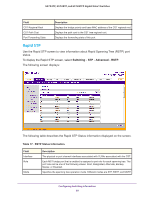
Switching, Advanced, CST Port, Status, PORTS, Table 16., CST Status Information.
 |
View all Netgear GS752TP manuals
Add to My Manuals
Save this manual to your list of manuals |
Page 98 highlights
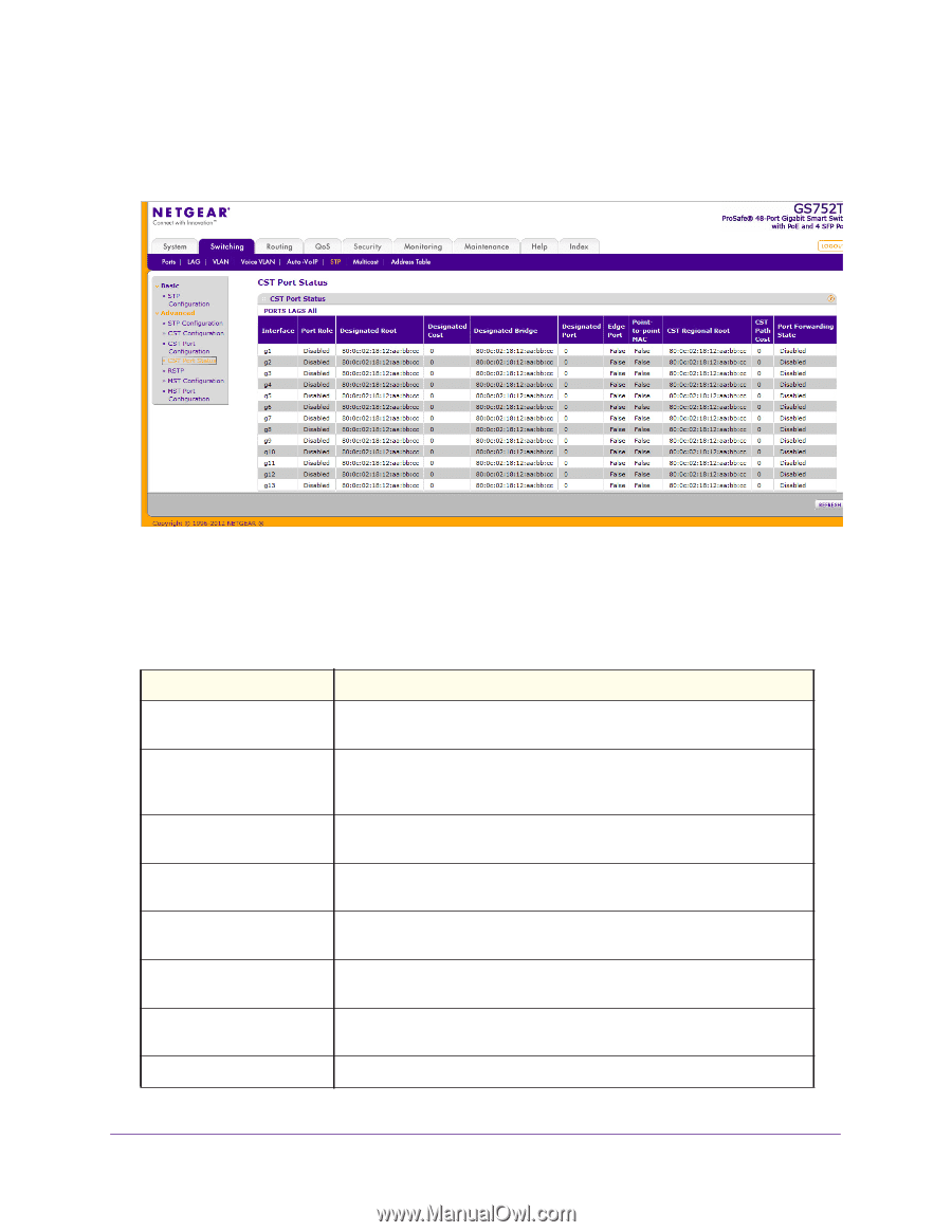
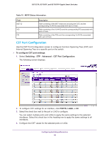
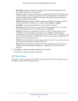
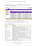
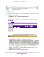
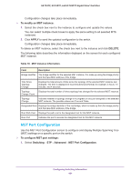
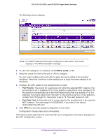
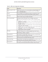
GS752TP, GS728TP, and GS728TPP Gigabit Smart Switches To display the CST Port Status screen, select Switching STP Advanced CST Port Status. The following screen displays: To view CST settings for an interface, click PORTS, LAGS, or All. The following table describes the CST Status information displayed on the screen. Table 16. CST Status Information. Field Interface Port Role Designated Root Designated Cost Designated Bridge Designated Port Edge Port Point-to-point MAC Description Select a physical or port channel interface to configure. The port is associated with the VLANs associated with the CST. Each MST Bridge Port that is enabled is assigned a port role for each spanning tree. The port role can be one of the following values: Root, Designated, Alternate, Backup, Master, or Disabled. Root bridge for the CST. It is made up using the bridge priority and the base MAC address of the bridge. Displays cost of the port participating in the STP topology. Ports with a lower cost are less likely to be blocked if STP detects loops. Bridge identifier of the bridge with the designated port. It is made up using the bridge priority and the base MAC address of the bridge. Port identifier on the designated bridge that offers the lowest cost to the LAN. It is made up from the port priority and the interface number of the port. Indicates whether the port is enabled as an edge port. Possible values are Enabled and Disabled. Derived value of the point-to-point status. Configuring Switching Information 98
-
 1
1 -
2
-
3
-
4
-
5
-
6
-
7
-
8
-
9
-
10
-
11
-
12
-
13
-
14
-
15
-
16
-
17
-
18
-
19
-
20
-
21
-
22
-
23
-
24
-
25
-
26
-
27
-
28
-
29
-
30
-
31
-
32
-
33
-
34
-
35
-
36
-
37
-
38
-
39
-
40
-
41
-
42
-
43
-
44
-
45
-
46
-
47
-
48
-
49
-
50
-
51
-
52
-
53
-
54
-
55
-
56
-
57
-
58
-
59
-
60
-
61
-
62
-
63
-
64
-
65
-
66
-
67
-
68
-
69
-
70
-
71
-
72
-
73
-
74
-
75
-
76
-
77
-
78
-
79
-
80
-
81
-
82
-
83
-
84
-
85
-
86
-
87
-
88
-
89
-
90
-
91
-
92
-
 93
93 -
 94
94 -
 95
95 -
 96
96 -
 97
97 -
 98
98 -
 99
99 -
 100
100 -
 101
101 -
 102
102 -
 103
103 -
104
-
105
-
106
-
107
-
108
-
109
-
110
-
111
-
112
-
113
-
114
-
115
-
116
-
117
-
118
-
119
-
120
-
121
-
122
-
123
-
124
-
125
-
126
-
127
-
128
-
129
-
130
-
131
-
132
-
133
-
134
-
135
-
136
-
137
-
138
-
139
-
140
-
141
-
142
-
143
-
144
-
145
-
146
-
147
-
148
-
149
-
150
-
151
-
152
-
153
-
154
-
155
-
156
-
157
-
158
-
159
-
160
-
161
-
162
-
163
-
164
-
165
-
166
-
167
-
168
-
169
-
170
-
171
-
172
-
173
-
174
-
175
-
176
-
177
-
178
-
179
-
180
-
181
-
182
-
183
-
184
-
185
-
186
-
187
-
188
-
189
-
190
-
191
-
192
-
193
-
194
-
195
-
196
-
197
-
198
-
199
-
200
-
201
-
202
-
203
-
204
-
205
-
206
-
207
-
208
-
209
-
210
-
211
-
212
-
213
-
214
-
215
-
216
-
217
-
218
-
219
-
220
-
221
-
222
-
223
-
224
-
225
-
226
-
227
-
228
-
229
-
230
-
231
-
232
-
233
-
234
-
235
-
236
-
237
-
238
-
239
-
240
-
241
-
242
-
243
-
244
-
245
-
246
-
247
-
248
-
249
-
250
-
251
-
252
-
253
-
254
-
255
-
256
-
257
-
258
-
259
-
260
-
261
-
262
-
263
-
264
-
265
-
266
-
267
-
268
-
269
-
270
-
271
-
272
-
273
-
274
-
275
 |
 |