Ricoh Aficio SP C320DN Manuals - Page 19
Exterior: Rear View, Front Cover Open Lever
 |
View all Ricoh Aficio SP C320DN manuals
Add to My Manuals
Save this manual to your list of manuals |
Page 19 highlights
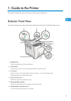
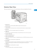
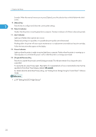
Exterior: Rear View Exterior: Rear View This section introduces the names and functions of the parts on the rear and right sides of the printer. 1 10 9 8 7 1 6 5 2 4 3 CBK013 1. Memory Cover Remove this cover to install the additional SDRAM module and hard disk (optional). 2. Power Connector Connect the power cord to the printer here. Insert the other end of the cable into a nearby wall outlet. 3. Rear Cover Remove this cover when you load paper larger than A4 in the paper tray. 4. Cable Cover Remove this cover to install the optional interface units and the SD card, and to connect various cables. 5. Front Cover Open Lever Pull this lever to open the front cover. 6. Optional Interface Board Slot Insert an optional Wireless LAN interface unit, Gigabit Ethernet board, or IEEE 1284 interface board in this slot. 7. USB Port A Use a USB cable to connect the printer to a digital camera. 8. SD Card Slots Remove the cover and install SD cards here. Install the data overwrite security unit, NetWare card or camera direct print card in the upper slot. Install the VM card or HDD encryption unit in the lower slot. 9. USB Port B Use a USB cable to connect the printer to a computer. 10. Ethernet Port Use a network interface cable to connect the printer to the network. 17
-
 1
1 -
2
-
3
-
4
-
5
-
6
-
7
-
8
-
9
-
10
-
11
-
12
-
13
-
 14
14 -
 15
15 -
 16
16 -
 17
17 -
 18
18 -
 19
19 -
 20
20 -
 21
21 -
 22
22 -
 23
23 -
 24
24 -
25
-
26
-
27
-
28
-
29
-
30
-
31
-
32
-
33
-
34
-
35
-
36
-
37
-
38
-
39
-
40
-
41
-
42
-
43
-
44
-
45
-
46
-
47
-
48
-
49
-
50
-
51
-
52
-
53
-
54
-
55
-
56
-
57
-
58
-
59
-
60
-
61
-
62
-
63
-
64
-
65
-
66
-
67
-
68
-
69
-
70
-
71
-
72
-
73
-
74
-
75
-
76
-
77
-
78
-
79
-
80
-
81
-
82
-
83
-
84
-
85
-
86
-
87
-
88
-
89
-
90
-
91
-
92
-
93
-
94
-
95
-
96
-
97
-
98
-
99
-
100
-
101
-
102
-
103
-
104
-
105
-
106
-
107
-
108
-
109
-
110
-
111
-
112
-
113
-
114
-
115
-
116
-
117
-
118
-
119
-
120
-
121
-
122
-
123
-
124
-
125
-
126
-
127
-
128
-
129
-
130
-
131
-
132
-
133
-
134
-
135
-
136
-
137
-
138
-
139
-
140
-
141
-
142
-
143
-
144
-
145
-
146
-
147
-
148
-
149
-
150
-
151
-
152
-
153
-
154
-
155
-
156
-
157
-
158
-
159
-
160
-
161
-
162
-
163
-
164
-
165
-
166
-
167
-
168
-
169
-
170
-
171
-
172
-
173
-
174
-
175
-
176
-
177
-
178
-
179
-
180
-
181
-
182
-
183
-
184
-
185
-
186
-
187
-
188
-
189
-
190
-
191
-
192
-
193
-
194
-
195
-
196
-
197
-
198
-
199
-
200
-
201
-
202
-
203
-
204
-
205
-
206
-
207
-
208
-
209
-
210
-
211
-
212
-
213
-
214
-
215
-
216
-
217
-
218
-
219
-
220
-
221
-
222
-
223
-
224
-
225
-
226
-
227
-
228
-
229
-
230
-
231
-
232
-
233
-
234
-
235
-
236
-
237
-
238
-
239
-
240
-
241
-
242
-
243
-
244
-
245
-
246
-
247
-
248
-
249
-
250
-
251
-
252
-
253
-
254
-
255
-
256
-
257
-
258
-
259
-
260
 |
 |
