Toshiba S1 User Manual - Page 44
Underside
 |
View all Toshiba S1 manuals
Add to My Manuals
Save this manual to your list of manuals |
Page 44 highlights
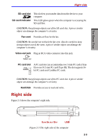
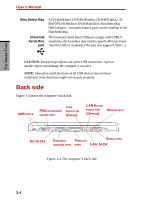
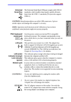
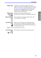
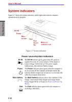
THE GRAND TOUR User's Manual External monitor This 15-pin port lets you connect an external monitor. port Parallel port Serial port This Centronics-compatible, 25-pin parallel port is used to connect a parallel printer or other parallel device. This port supports Extended Capabilities Port (ECP) standard. Use this 9-pin port to connect external serial devices such as an external modem, a serial mouse or printer. Underside Figure 2-5 shows the underside of the computer. Make sure the display is closed before turning over your computer. SLIM SELECT BAY LOCK SLIM SELECT BAY LATCH DOCKING HOLE DOCKING PORT DOCKING HOLE MEMORY MODULE COVER BATTERY PACK COVER LATCH BATTERY PACK Figure 2-5 The underside of the computer Docking holes Docking port These holes ensure a proper connection between the computer and an optional Port Replicator. Use this port to connect an optional Port Replicator. CAUTION: Keep foreign objects out of the docking port. A pin or similar object can damage the computer's circuitry. 2-6
-
 1
1 -
2
-
3
-
4
-
5
-
6
-
7
-
8
-
9
-
10
-
11
-
12
-
13
-
14
-
15
-
16
-
17
-
18
-
19
-
20
-
21
-
22
-
23
-
24
-
25
-
26
-
27
-
28
-
29
-
30
-
31
-
32
-
33
-
34
-
35
-
36
-
37
-
38
-
 39
39 -
 40
40 -
 41
41 -
 42
42 -
 43
43 -
 44
44 -
 45
45 -
 46
46 -
 47
47 -
 48
48 -
 49
49 -
50
-
51
-
52
-
53
-
54
-
55
-
56
-
57
-
58
-
59
-
60
-
61
-
62
-
63
-
64
-
65
-
66
-
67
-
68
-
69
-
70
-
71
-
72
-
73
-
74
-
75
-
76
-
77
-
78
-
79
-
80
-
81
-
82
-
83
-
84
-
85
-
86
-
87
-
88
-
89
-
90
-
91
-
92
-
93
-
94
-
95
-
96
-
97
-
98
-
99
-
100
-
101
-
102
-
103
-
104
-
105
-
106
-
107
-
108
-
109
-
110
-
111
-
112
-
113
-
114
-
115
-
116
-
117
-
118
-
119
-
120
-
121
-
122
-
123
-
124
-
125
-
126
-
127
-
128
-
129
-
130
-
131
-
132
-
133
-
134
-
135
-
136
-
137
-
138
-
139
-
140
-
141
-
142
-
143
-
144
-
145
-
146
-
147
-
148
-
149
-
150
-
151
-
152
-
153
-
154
-
155
-
156
-
157
-
158
-
159
-
160
-
161
-
162
-
163
-
164
-
165
-
166
-
167
-
168
-
169
-
170
-
171
-
172
-
173
-
174
-
175
-
176
-
177
-
178
-
179
-
180
-
181
-
182
-
183
-
184
-
185
-
186
-
187
-
188
-
189
-
190
-
191
-
192
-
193
-
194
-
195
-
196
-
197
-
198
-
199
-
200
-
201
-
202
-
203
-
204
-
205
-
206
-
207
-
208
-
209
-
210
-
211
-
212
-
213
-
214
-
215
-
216
-
217
-
218
-
219
-
220
-
221
-
222
-
223
-
224
-
225
-
226
-
227
-
228
-
229
-
230
-
231
-
232
-
233
-
234
-
235
-
236
 |
 |