Toshiba S1 User Manual - Page 45
Battery pack, cover latch, Memory module, cover, Slim Select Bay, latch, Power and Power-Up Modes
 |
View all Toshiba S1 manuals
Add to My Manuals
Save this manual to your list of manuals |
Page 45 highlights
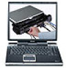
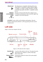
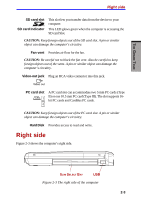
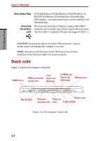
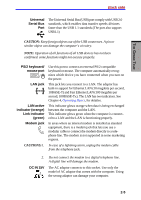
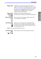
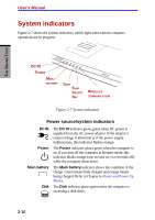
THE GRAND TOUR Underside Battery pack Battery pack cover latch The battery pack powers the computer when the AC adaptor is not connected. The Batteries section in Chapter 6, Power and Power-Up Modes, describes how to access the battery pack. Additional battery packs can be purchased from your TOSHIBA dealer to extend the computer's battery operating time. Slide this latch to release or the battery pack. This latch moves only when the computer is upside down. Memory module This cover protects two memory module sockets. One cover or two modules are preinstalled. Slim Select Bay lock There are two screw holes next to the Slim Select Bay latch. One screw is initially set in the front hole, which is the unlock position. To lock the Slim Select Bay latch, set the screw in the back hole. NOTE: Use a point size 0 Phillips screwdriver. Slim Select Bay Slide this latch to free the Slim Select Bay for removal. latch 2-7
-
 1
1 -
2
-
3
-
4
-
5
-
6
-
7
-
8
-
9
-
10
-
11
-
12
-
13
-
14
-
15
-
16
-
17
-
18
-
19
-
20
-
21
-
22
-
23
-
24
-
25
-
26
-
27
-
28
-
29
-
30
-
31
-
32
-
33
-
34
-
35
-
36
-
37
-
38
-
39
-
 40
40 -
 41
41 -
 42
42 -
 43
43 -
 44
44 -
 45
45 -
 46
46 -
 47
47 -
 48
48 -
 49
49 -
 50
50 -
51
-
52
-
53
-
54
-
55
-
56
-
57
-
58
-
59
-
60
-
61
-
62
-
63
-
64
-
65
-
66
-
67
-
68
-
69
-
70
-
71
-
72
-
73
-
74
-
75
-
76
-
77
-
78
-
79
-
80
-
81
-
82
-
83
-
84
-
85
-
86
-
87
-
88
-
89
-
90
-
91
-
92
-
93
-
94
-
95
-
96
-
97
-
98
-
99
-
100
-
101
-
102
-
103
-
104
-
105
-
106
-
107
-
108
-
109
-
110
-
111
-
112
-
113
-
114
-
115
-
116
-
117
-
118
-
119
-
120
-
121
-
122
-
123
-
124
-
125
-
126
-
127
-
128
-
129
-
130
-
131
-
132
-
133
-
134
-
135
-
136
-
137
-
138
-
139
-
140
-
141
-
142
-
143
-
144
-
145
-
146
-
147
-
148
-
149
-
150
-
151
-
152
-
153
-
154
-
155
-
156
-
157
-
158
-
159
-
160
-
161
-
162
-
163
-
164
-
165
-
166
-
167
-
168
-
169
-
170
-
171
-
172
-
173
-
174
-
175
-
176
-
177
-
178
-
179
-
180
-
181
-
182
-
183
-
184
-
185
-
186
-
187
-
188
-
189
-
190
-
191
-
192
-
193
-
194
-
195
-
196
-
197
-
198
-
199
-
200
-
201
-
202
-
203
-
204
-
205
-
206
-
207
-
208
-
209
-
210
-
211
-
212
-
213
-
214
-
215
-
216
-
217
-
218
-
219
-
220
-
221
-
222
-
223
-
224
-
225
-
226
-
227
-
228
-
229
-
230
-
231
-
232
-
233
-
234
-
235
-
236
 |
 |