ZyXEL MI-7248 User Guide - Page 207
VRRP Configuration
 |
View all ZyXEL MI-7248 manuals
Add to My Manuals
Save this manual to your list of manuals |
Page 207 highlights
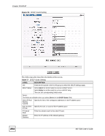
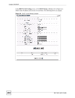
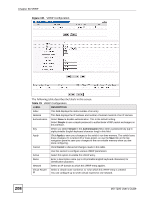
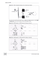
Chapter 36 VRRP The following table describes the labels in this screen. Table 78 VRRP Status LABEL DESCRIPTION Index This field displays the index number of a rule. Network This field displays the IP address and the subnet mask bits of an IP routing domain that is associated to a virtual router. VRID This field displays the ID number of the virtual router. VR Status This field displays the status of the virtual router. This field is Master indicating that this switch functions as the master router. This field is Backup indicating that this switch functions as a backup router. This field displays Init when this switch is initiating the VRRP protocol or when the Uplink Status field displays Dead. Uplink Status This field displays the status of the link between this switch and the uplink gateway. This field is Alive indicating that the link between this switch and the uplink gateway is up. Otherwise, this field is Dead. This field displays Probe when this switch is check for the link state. 36.2.1 VRRP Configuration Use this screen to specify the virtual routers in which the switch participates. Before configuring VRRP, first create an IP interface (or routing domain) in the IP Setup screen. See Section 10.2 on page 73 for more information. " You can only configure VRRP on interfaces with unique VLAN IDs. Routing domains with the same VLAN ID are not displayed in the table indicated. To open this screen, click IP Application > VRRP > Configuration. MS-7206 User's Guide 207
-
 1
1 -
2
-
3
-
4
-
5
-
6
-
7
-
8
-
9
-
10
-
11
-
12
-
13
-
14
-
15
-
16
-
17
-
18
-
19
-
20
-
21
-
22
-
23
-
24
-
25
-
26
-
27
-
28
-
29
-
30
-
31
-
32
-
33
-
34
-
35
-
36
-
37
-
38
-
39
-
40
-
41
-
42
-
43
-
44
-
45
-
46
-
47
-
48
-
49
-
50
-
51
-
52
-
53
-
54
-
55
-
56
-
57
-
58
-
59
-
60
-
61
-
62
-
63
-
64
-
65
-
66
-
67
-
68
-
69
-
70
-
71
-
72
-
73
-
74
-
75
-
76
-
77
-
78
-
79
-
80
-
81
-
82
-
83
-
84
-
85
-
86
-
87
-
88
-
89
-
90
-
91
-
92
-
93
-
94
-
95
-
96
-
97
-
98
-
99
-
100
-
101
-
102
-
103
-
104
-
105
-
106
-
107
-
108
-
109
-
110
-
111
-
112
-
113
-
114
-
115
-
116
-
117
-
118
-
119
-
120
-
121
-
122
-
123
-
124
-
125
-
126
-
127
-
128
-
129
-
130
-
131
-
132
-
133
-
134
-
135
-
136
-
137
-
138
-
139
-
140
-
141
-
142
-
143
-
144
-
145
-
146
-
147
-
148
-
149
-
150
-
151
-
152
-
153
-
154
-
155
-
156
-
157
-
158
-
159
-
160
-
161
-
162
-
163
-
164
-
165
-
166
-
167
-
168
-
169
-
170
-
171
-
172
-
173
-
174
-
175
-
176
-
177
-
178
-
179
-
180
-
181
-
182
-
183
-
184
-
185
-
186
-
187
-
188
-
189
-
190
-
191
-
192
-
193
-
194
-
195
-
196
-
197
-
198
-
199
-
200
-
201
-
 202
202 -
 203
203 -
 204
204 -
 205
205 -
 206
206 -
 207
207 -
 208
208 -
 209
209 -
 210
210 -
 211
211 -
 212
212 -
213
-
214
-
215
-
216
-
217
-
218
-
219
-
220
-
221
-
222
-
223
-
224
-
225
-
226
-
227
-
228
-
229
-
230
-
231
-
232
-
233
-
234
-
235
-
236
-
237
-
238
-
239
-
240
-
241
-
242
-
243
-
244
-
245
-
246
-
247
-
248
-
249
-
250
-
251
-
252
-
253
-
254
-
255
-
256
-
257
-
258
-
259
-
260
-
261
-
262
-
263
-
264
-
265
-
266
-
267
-
268
-
269
-
270
-
271
-
272
-
273
-
274
-
275
-
276
-
277
-
278
-
279
-
280
-
281
-
282
-
283
-
284
-
285
-
286
-
287
-
288
-
289
-
290
-
291
-
292
-
293
-
294
-
295
-
296
-
297
-
298
-
299
-
300
-
301
-
302
-
303
-
304
-
305
-
306
-
307
-
308
-
309
-
310
 |
 |