ZyXEL MI-7248 User Guide - Page 53
Initial Setup Example
 |
View all ZyXEL MI-7248 manuals
Add to My Manuals
Save this manual to your list of manuals |
Page 53 highlights
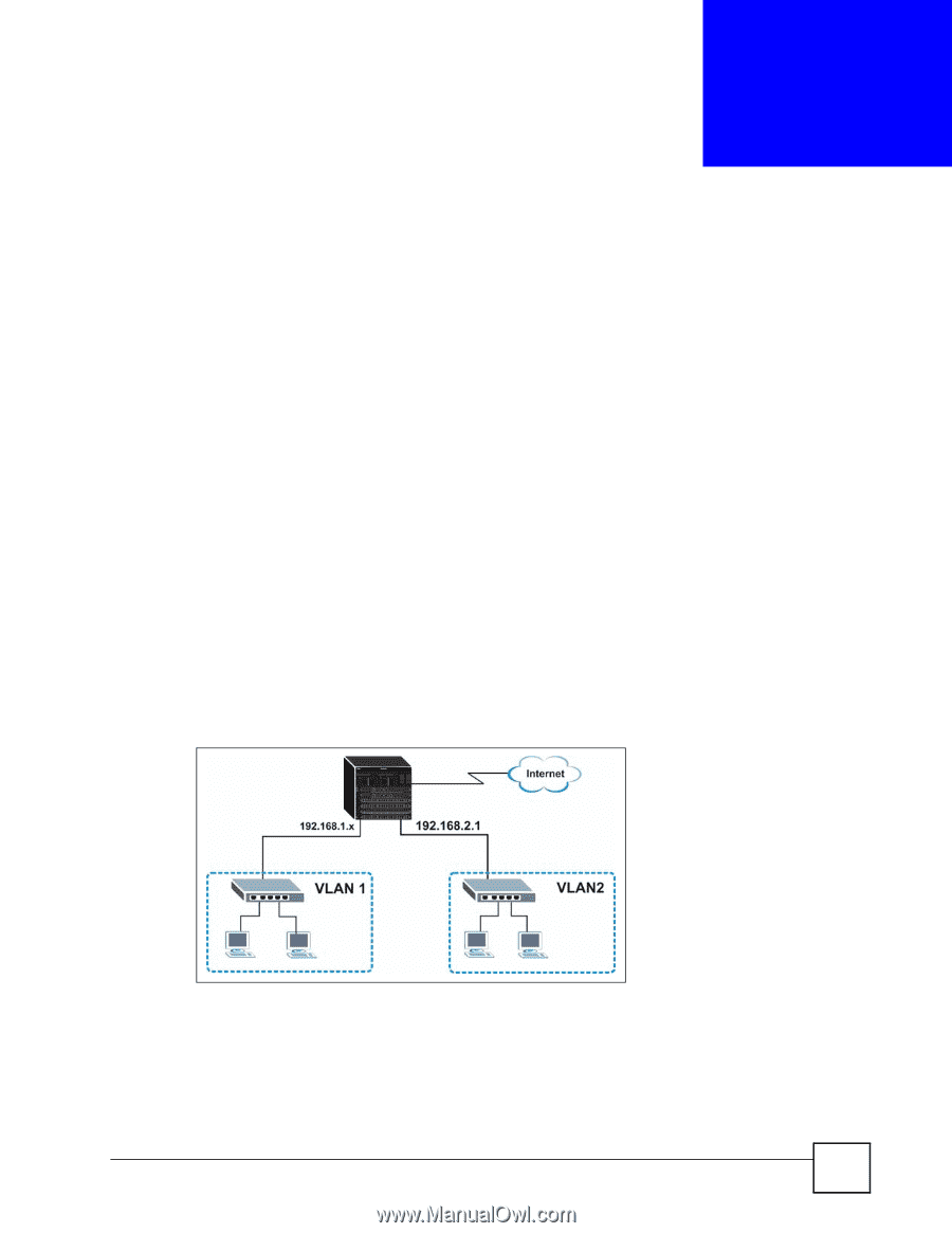
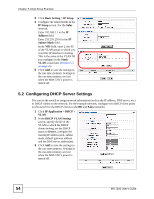
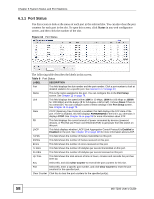
CHAPTER 5 Initial Setup Example This chapter explains how to complete the following steps for an example network. • Configure an IP interface • Configure DHCP server settings • Create a VLAN • Set port VLAN ID • Enable RIP 5.1 Configuring an IP Interface On a layer-3 switch, an IP interface (also known as an IP routing domain) is not bound to a physical port. The default out-of-band IP address of the switch is 192.168.0.1 with a subnet mask of 255.255.255.0. The default in-band IP address of the switch is 192.168.1.1 with a subnet mask of 255.255.255.0. In the example network, since the RD (VLAN 1) network is already in the same IP interface as the switch, you don't need to create an IP interface for it. However, if you want to have the Sales (VLAN 2) network on a different routing domain, you need to create a new IP interface. This allows the switch to route traffic between the RD and Sales networks. Figure 12 Initial Setup Network Example: IP Interface 1 Connect your computer to the out-of-band MGMT port that is used only for management. Make sure your computer is in the same subnet as the MGMT port. 2 Open your web browser and enter http://192.168.0.1 (the default MGMT port IP address) in the address bar to access the web configurator. See Section 4.2 on page 45 for more information. MS-7206 User's Guide 53
-
 1
1 -
2
-
3
-
4
-
5
-
6
-
7
-
8
-
9
-
10
-
11
-
12
-
13
-
14
-
15
-
16
-
17
-
18
-
19
-
20
-
21
-
22
-
23
-
24
-
25
-
26
-
27
-
28
-
29
-
30
-
31
-
32
-
33
-
34
-
35
-
36
-
37
-
38
-
39
-
40
-
41
-
42
-
43
-
44
-
45
-
46
-
47
-
 48
48 -
 49
49 -
 50
50 -
 51
51 -
 52
52 -
 53
53 -
 54
54 -
 55
55 -
 56
56 -
 57
57 -
 58
58 -
59
-
60
-
61
-
62
-
63
-
64
-
65
-
66
-
67
-
68
-
69
-
70
-
71
-
72
-
73
-
74
-
75
-
76
-
77
-
78
-
79
-
80
-
81
-
82
-
83
-
84
-
85
-
86
-
87
-
88
-
89
-
90
-
91
-
92
-
93
-
94
-
95
-
96
-
97
-
98
-
99
-
100
-
101
-
102
-
103
-
104
-
105
-
106
-
107
-
108
-
109
-
110
-
111
-
112
-
113
-
114
-
115
-
116
-
117
-
118
-
119
-
120
-
121
-
122
-
123
-
124
-
125
-
126
-
127
-
128
-
129
-
130
-
131
-
132
-
133
-
134
-
135
-
136
-
137
-
138
-
139
-
140
-
141
-
142
-
143
-
144
-
145
-
146
-
147
-
148
-
149
-
150
-
151
-
152
-
153
-
154
-
155
-
156
-
157
-
158
-
159
-
160
-
161
-
162
-
163
-
164
-
165
-
166
-
167
-
168
-
169
-
170
-
171
-
172
-
173
-
174
-
175
-
176
-
177
-
178
-
179
-
180
-
181
-
182
-
183
-
184
-
185
-
186
-
187
-
188
-
189
-
190
-
191
-
192
-
193
-
194
-
195
-
196
-
197
-
198
-
199
-
200
-
201
-
202
-
203
-
204
-
205
-
206
-
207
-
208
-
209
-
210
-
211
-
212
-
213
-
214
-
215
-
216
-
217
-
218
-
219
-
220
-
221
-
222
-
223
-
224
-
225
-
226
-
227
-
228
-
229
-
230
-
231
-
232
-
233
-
234
-
235
-
236
-
237
-
238
-
239
-
240
-
241
-
242
-
243
-
244
-
245
-
246
-
247
-
248
-
249
-
250
-
251
-
252
-
253
-
254
-
255
-
256
-
257
-
258
-
259
-
260
-
261
-
262
-
263
-
264
-
265
-
266
-
267
-
268
-
269
-
270
-
271
-
272
-
273
-
274
-
275
-
276
-
277
-
278
-
279
-
280
-
281
-
282
-
283
-
284
-
285
-
286
-
287
-
288
-
289
-
290
-
291
-
292
-
293
-
294
-
295
-
296
-
297
-
298
-
299
-
300
-
301
-
302
-
303
-
304
-
305
-
306
-
307
-
308
-
309
-
310
 |
 |