ZyXEL MI-7248 User Guide - Page 64
LABEL, DESCRIPTION, Basic Setting > General Setup, Management > Maintenance > Firmware
 |
View all ZyXEL MI-7248 manuals
Add to My Manuals
Save this manual to your list of manuals |
Page 64 highlights
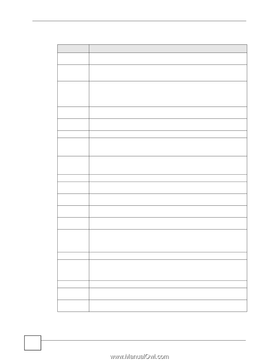
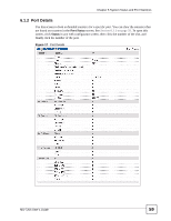
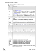
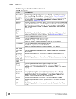
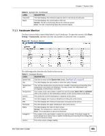
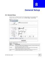
Chapter 7 System Info The following table describes the labels in this screen. Table 8 System Info LABEL DESCRIPTION System Name This field displays the descriptive name of the MM-7201 for identification purposes. Click Basic Setting > General Setup to change this. See Chapter 8 on page 67. ZyNOS F/W Version This field displays the version number of the MM-7201's current firmware including the date created. Click Management > Maintenance > Firmware Upgrade to change this. See Chapter 37 on page 215. Ethernet Address This field displays the Ethernet MAC (Media Access Control) address of the MS-7206 system. The MS-7206 system copies the MAC address from the active management card when the MS-7206 system starts up. The MS-7206 system keeps using this MAC address, even if the standby management card takes over, until the system starts up again. Hardware Status Slot This field displays the slots that have a card installed in them. Click a slot number to look at more detail about the card's hardware. See Section 7.1.1 on page 65. Name This field displays the type of card in the slot. Voltage This field displays the voltage status in the card. Normal: The voltage is within allowable range. Error: The voltage is outside the allowable range at one or more sensors. Temperature This field displays the temperature status in the card. Normal: The temperature is below the threshold. Error: The temperature is above the threshold at one or more sensors. PoE Status Total Power (W) This field displays the total amount of power available from a Power over Ethernet (PoE) injector. Consuming Power (W) This field displays the amount of power from a PoE injector the system is using. Remaining Power (W) This field displays the amount of power from a PoE injector the system is not using. Power Source Status Power1 Power2 This field displays the status of each power module in the system. Present: There is a power module in this slot, and it is working properly. Absent: There is no power module in this slot, or the power module is not working properly. FAN Status Fan Speed (RPM) A properly functioning fan is an essential component (along with a sufficiently ventilated, cool operating environment) in order for the system to stay within the temperature threshold. Each fan has a sensor that is capable of detecting and reporting if the fan speed falls below the threshold shown. Current This field displays this fan's current speed in Revolutions Per Minute (RPM). MAX This field displays this fan's maximum speed measured in Revolutions Per Minute (RPM). MIN This field displays this fan's minimum speed measured in Revolutions Per Minute (RPM). 64 MS-7206 User's Guide
-
 1
1 -
2
-
3
-
4
-
5
-
6
-
7
-
8
-
9
-
10
-
11
-
12
-
13
-
14
-
15
-
16
-
17
-
18
-
19
-
20
-
21
-
22
-
23
-
24
-
25
-
26
-
27
-
28
-
29
-
30
-
31
-
32
-
33
-
34
-
35
-
36
-
37
-
38
-
39
-
40
-
41
-
42
-
43
-
44
-
45
-
46
-
47
-
48
-
49
-
50
-
51
-
52
-
53
-
54
-
55
-
56
-
57
-
58
-
 59
59 -
 60
60 -
 61
61 -
 62
62 -
 63
63 -
 64
64 -
 65
65 -
 66
66 -
 67
67 -
 68
68 -
 69
69 -
70
-
71
-
72
-
73
-
74
-
75
-
76
-
77
-
78
-
79
-
80
-
81
-
82
-
83
-
84
-
85
-
86
-
87
-
88
-
89
-
90
-
91
-
92
-
93
-
94
-
95
-
96
-
97
-
98
-
99
-
100
-
101
-
102
-
103
-
104
-
105
-
106
-
107
-
108
-
109
-
110
-
111
-
112
-
113
-
114
-
115
-
116
-
117
-
118
-
119
-
120
-
121
-
122
-
123
-
124
-
125
-
126
-
127
-
128
-
129
-
130
-
131
-
132
-
133
-
134
-
135
-
136
-
137
-
138
-
139
-
140
-
141
-
142
-
143
-
144
-
145
-
146
-
147
-
148
-
149
-
150
-
151
-
152
-
153
-
154
-
155
-
156
-
157
-
158
-
159
-
160
-
161
-
162
-
163
-
164
-
165
-
166
-
167
-
168
-
169
-
170
-
171
-
172
-
173
-
174
-
175
-
176
-
177
-
178
-
179
-
180
-
181
-
182
-
183
-
184
-
185
-
186
-
187
-
188
-
189
-
190
-
191
-
192
-
193
-
194
-
195
-
196
-
197
-
198
-
199
-
200
-
201
-
202
-
203
-
204
-
205
-
206
-
207
-
208
-
209
-
210
-
211
-
212
-
213
-
214
-
215
-
216
-
217
-
218
-
219
-
220
-
221
-
222
-
223
-
224
-
225
-
226
-
227
-
228
-
229
-
230
-
231
-
232
-
233
-
234
-
235
-
236
-
237
-
238
-
239
-
240
-
241
-
242
-
243
-
244
-
245
-
246
-
247
-
248
-
249
-
250
-
251
-
252
-
253
-
254
-
255
-
256
-
257
-
258
-
259
-
260
-
261
-
262
-
263
-
264
-
265
-
266
-
267
-
268
-
269
-
270
-
271
-
272
-
273
-
274
-
275
-
276
-
277
-
278
-
279
-
280
-
281
-
282
-
283
-
284
-
285
-
286
-
287
-
288
-
289
-
290
-
291
-
292
-
293
-
294
-
295
-
296
-
297
-
298
-
299
-
300
-
301
-
302
-
303
-
304
-
305
-
306
-
307
-
308
-
309
-
310
 |
 |