ZyXEL MI-7248 User Guide - Page 209
VRRP Configuration Examples
 |
View all ZyXEL MI-7248 manuals
Add to My Manuals
Save this manual to your list of manuals |
Page 209 highlights
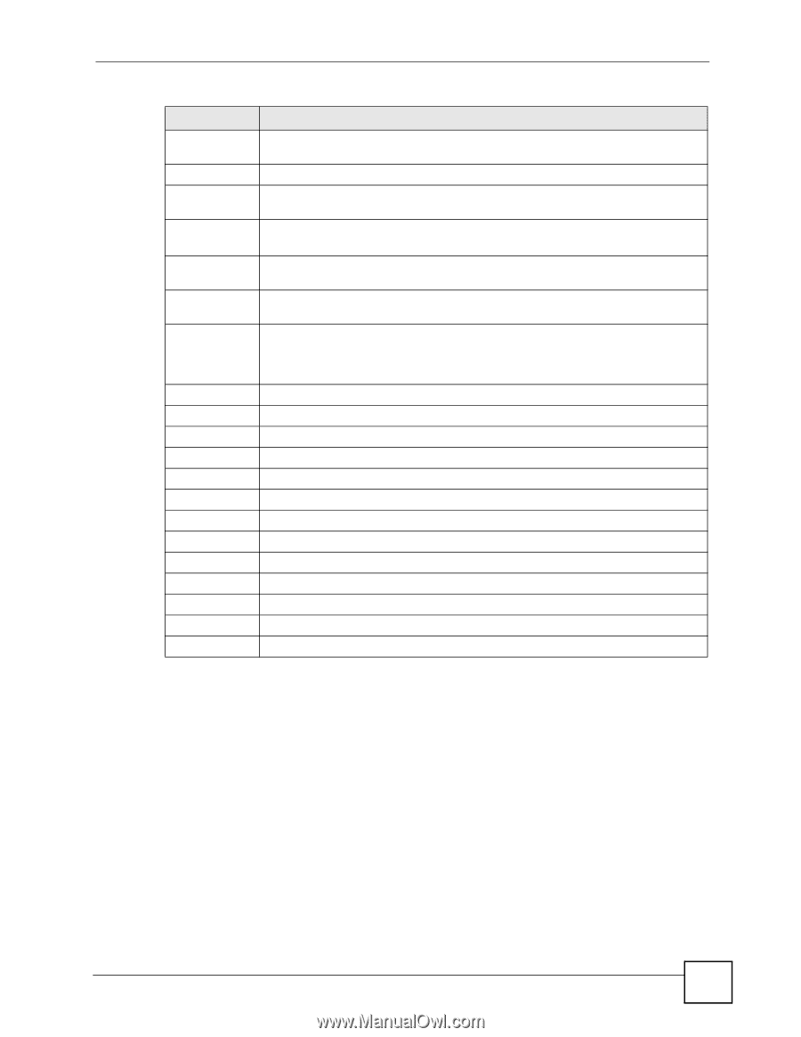
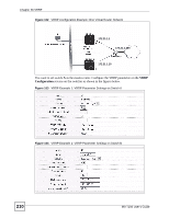
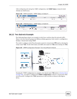
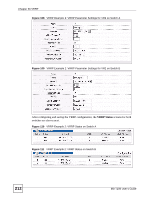
Chapter 36 VRRP Table 79 VRRP Configuration (continued) LABEL DESCRIPTION Advertisement Specify the number of seconds between Hello message transmissions. Interval Preempt Mode Select this option to activate preempt mode. Priority Enter a number (between 1 and 254) to set the priority level. The bigger the number, the higher the priority. Uplink Gateway Enter the IP address of the uplink gateway in dotted decimal notation. The switch checks the link to the uplink gateway. Primary Virtual Enter the IP address of the primary virtual router in dotted decimal notation. IP Secondary Virtual IP This field is optional. Enter the IP address of a secondary virtual router in dotted decimal notation. This field is ignored when you enter 0.0.0.0. Add Click Add to save your changes to the switch's run-time memory. The switch loses these changes if it is turned off or loses power, so use the Save link on the top navigation panel to save your changes to the non-volatile memory when you are done configuring. Cancel Click Cancel to discard all changes made in this table. Clear Click Clear to set the above fields back to the factory defaults. Use this section to look at a summary of VRRP configuration. Index This field displays the index number of an entry. Active This field shows whether a VRRP entry is enabled (Yes) or disabled (No). Name This field displays a descriptive name of an entry. Network This field displays the IP address and subnet mask of an interface. VRID This field displays the ID number of a virtual router. Primary VIP This field displays the IP address of the primary virtual router. Uplink Gateway This field displays the IP address of the uplink gateway. Priority This field displays the priority level (1 to 255) of the entry. Delete Click Delete to remove the selected entry from the summary table. Cancel Click Cancel to clear the Delete check boxes. 36.3 VRRP Configuration Examples The following sections show two VRRP configuration examples on the switch. 36.3.1 One Subnet Network Example The figure below shows a simple VRRP network with only one virtual router VR1 (VRID =1) and two switches. The network is connected to the WAN via an uplink gateway G (172.21.1.100). The host computer X is set to use VR1 as the default gateway. MS-7206 User's Guide 209
-
 1
1 -
2
-
3
-
4
-
5
-
6
-
7
-
8
-
9
-
10
-
11
-
12
-
13
-
14
-
15
-
16
-
17
-
18
-
19
-
20
-
21
-
22
-
23
-
24
-
25
-
26
-
27
-
28
-
29
-
30
-
31
-
32
-
33
-
34
-
35
-
36
-
37
-
38
-
39
-
40
-
41
-
42
-
43
-
44
-
45
-
46
-
47
-
48
-
49
-
50
-
51
-
52
-
53
-
54
-
55
-
56
-
57
-
58
-
59
-
60
-
61
-
62
-
63
-
64
-
65
-
66
-
67
-
68
-
69
-
70
-
71
-
72
-
73
-
74
-
75
-
76
-
77
-
78
-
79
-
80
-
81
-
82
-
83
-
84
-
85
-
86
-
87
-
88
-
89
-
90
-
91
-
92
-
93
-
94
-
95
-
96
-
97
-
98
-
99
-
100
-
101
-
102
-
103
-
104
-
105
-
106
-
107
-
108
-
109
-
110
-
111
-
112
-
113
-
114
-
115
-
116
-
117
-
118
-
119
-
120
-
121
-
122
-
123
-
124
-
125
-
126
-
127
-
128
-
129
-
130
-
131
-
132
-
133
-
134
-
135
-
136
-
137
-
138
-
139
-
140
-
141
-
142
-
143
-
144
-
145
-
146
-
147
-
148
-
149
-
150
-
151
-
152
-
153
-
154
-
155
-
156
-
157
-
158
-
159
-
160
-
161
-
162
-
163
-
164
-
165
-
166
-
167
-
168
-
169
-
170
-
171
-
172
-
173
-
174
-
175
-
176
-
177
-
178
-
179
-
180
-
181
-
182
-
183
-
184
-
185
-
186
-
187
-
188
-
189
-
190
-
191
-
192
-
193
-
194
-
195
-
196
-
197
-
198
-
199
-
200
-
201
-
202
-
203
-
 204
204 -
 205
205 -
 206
206 -
 207
207 -
 208
208 -
 209
209 -
 210
210 -
 211
211 -
 212
212 -
 213
213 -
 214
214 -
215
-
216
-
217
-
218
-
219
-
220
-
221
-
222
-
223
-
224
-
225
-
226
-
227
-
228
-
229
-
230
-
231
-
232
-
233
-
234
-
235
-
236
-
237
-
238
-
239
-
240
-
241
-
242
-
243
-
244
-
245
-
246
-
247
-
248
-
249
-
250
-
251
-
252
-
253
-
254
-
255
-
256
-
257
-
258
-
259
-
260
-
261
-
262
-
263
-
264
-
265
-
266
-
267
-
268
-
269
-
270
-
271
-
272
-
273
-
274
-
275
-
276
-
277
-
278
-
279
-
280
-
281
-
282
-
283
-
284
-
285
-
286
-
287
-
288
-
289
-
290
-
291
-
292
-
293
-
294
-
295
-
296
-
297
-
298
-
299
-
300
-
301
-
302
-
303
-
304
-
305
-
306
-
307
-
308
-
309
-
310
 |
 |