Cisco 2950 Hardware Installation Guide - Page 106
Four Twisted-Pair Cable Pinouts for 1000BASE-T Ports, RJ-21 Cable Pinouts
 |
UPC - 746320454504
View all Cisco 2950 manuals
Add to My Manuals
Save this manual to your list of manuals |
Page 106 highlights
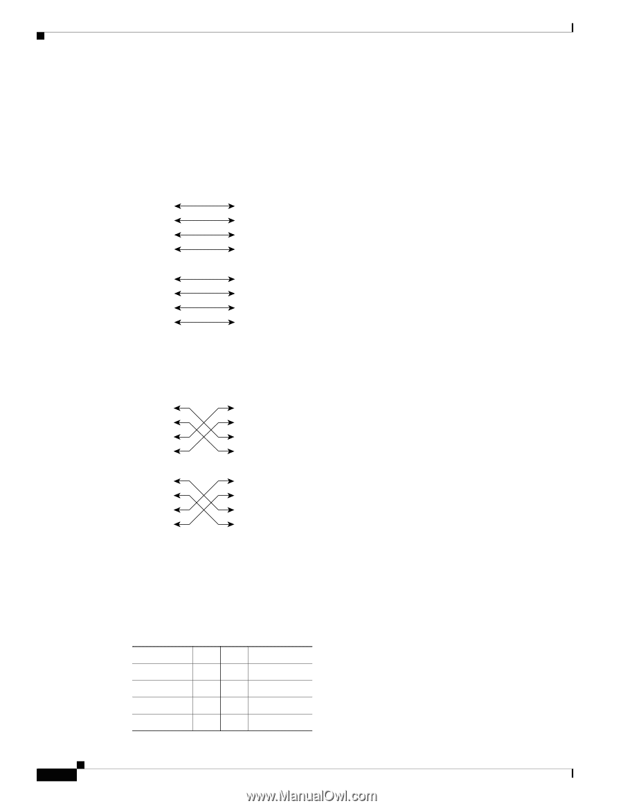
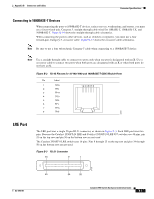
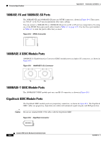
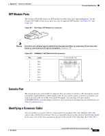
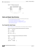
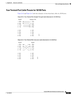
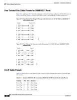
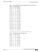
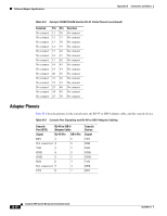
Cable and Adapter Specifications Appendix B Connectors and Cables Four Twisted-Pair Cable Pinouts for 1000BASE-T Ports Figure B-14 and Figure B-15 show the schematics of four twisted-pair cables for 10/100/1000 ports on Catalyst 2950T-24 switches, Catalyst 2950 LRE switches, and 1000BASE-T GBIC module ports. Figure B-14 Four Twisted-Pair Straight-Through Cable Schematic for 10/100/1000 and 1000BASE-T GBIC Module Ports Switch 1 TPO+ 2 TPO3 TP1+ 6 TP1- Router or PC 1 TP1+ 2 TP13 TPO+ 6 TPO- 4 TP2+ 5 TP27 TP3+ 8 TP3- 4 TP3+ 5 TP37 TP2+ 8 TP2- 65272 Figure B-15 Four Twisted-Pair Crossover Cable Schematics for 10/100/1000 and 1000BASE-T GBIC Module Ports Switch 1 TPO+ 2 TPO3 TP1+ 6 TP1- Switch 1 TP0+ 2 TP03 TP1+ 6 TP1- 4 TP2+ 5 TP27 TP3+ 8 TP3- 4 TP2+ 5 TP27 TP3+ 8 TP3- 65274 RJ-21 Cable Pinouts Table B-1 lists the RJ-21 cable pinouts on the Catalyst 2950ST-24 LRE and Catalyst 2950ST-24 LRE 997 switches. Table B-1 Catalyst 2950ST-24 LRE and Catalyst 2950ST-24 LRE 997 Switch RJ-21 Cable Pinouts Function Port 1 Tip Port 2 Tip Port 3 Tip Port 4 Tip Pin Pin Function 1 26 Port 1 Ring 2 27 Port 2 Ring 3 28 Port 3 Ring 4 29 Port 4 Ring Catalyst 2950 Switch Hardware Installation Guide B-8 OL-6156-01
-
 1
1 -
2
-
3
-
4
-
5
-
6
-
7
-
8
-
9
-
10
-
11
-
12
-
13
-
14
-
15
-
16
-
17
-
18
-
19
-
20
-
21
-
22
-
23
-
24
-
25
-
26
-
27
-
28
-
29
-
30
-
31
-
32
-
33
-
34
-
35
-
36
-
37
-
38
-
39
-
40
-
41
-
42
-
43
-
44
-
45
-
46
-
47
-
48
-
49
-
50
-
51
-
52
-
53
-
54
-
55
-
56
-
57
-
58
-
59
-
60
-
61
-
62
-
63
-
64
-
65
-
66
-
67
-
68
-
69
-
70
-
71
-
72
-
73
-
74
-
75
-
76
-
77
-
78
-
79
-
80
-
81
-
82
-
83
-
84
-
85
-
86
-
87
-
88
-
89
-
90
-
91
-
92
-
93
-
94
-
95
-
96
-
97
-
98
-
99
-
100
-
 101
101 -
 102
102 -
 103
103 -
 104
104 -
 105
105 -
 106
106 -
 107
107 -
 108
108 -
 109
109 -
 110
110 -
 111
111 -
112
-
113
-
114
-
115
-
116
-
117
-
118
-
119
-
120
-
121
-
122
-
123
-
124
-
125
-
126
-
127
-
128
-
129
-
130
-
131
-
132
-
133
-
134
 |
 |