Cisco 2950 Hardware Installation Guide - Page 33
LEDs, for the Catalyst 2950ST-8 LRE and 2950ST-24 LRE switches - 2950t
 |
UPC - 746320454504
View all Cisco 2950 manuals
Add to My Manuals
Save this manual to your list of manuals |
Page 33 highlights
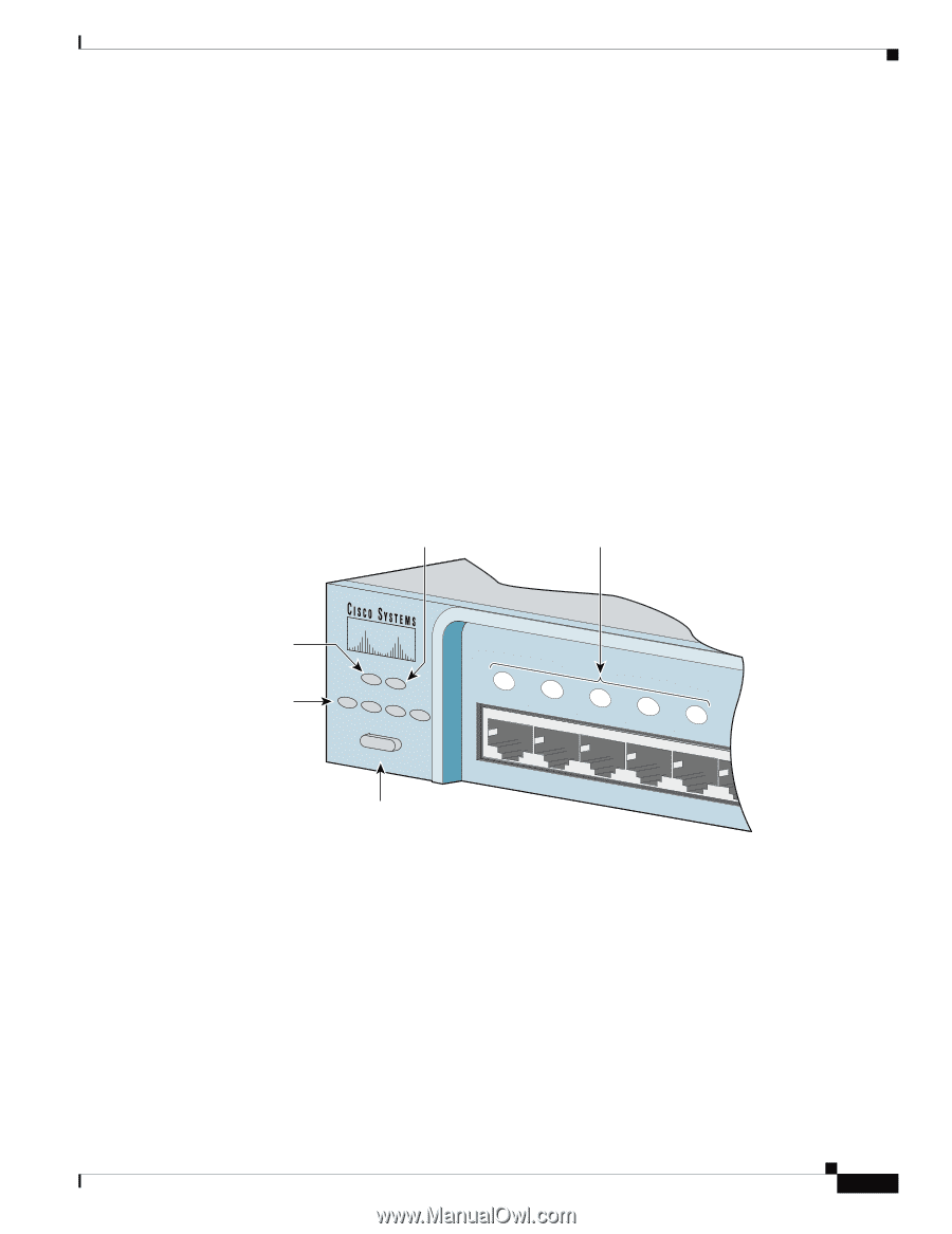
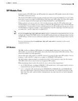
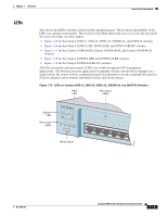
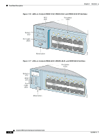
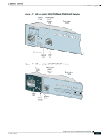
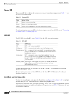
Chapter 1 Overview Front-Panel Description LEDs You can use the LEDs to monitor switch activity and performance. The locations and numbers of the LEDs vary among switch models. The location of the Mode button that you use to select the port mode also varies by model. See these figures: • Figure 1-15 for the Catalyst 2950-12, 2950-24, 2950C-24, 2950SX-24, and 2950T-24 switches • Figure 1-16 for the Catalyst 2950G-12-EI, 2950G-24-EI, and 2950G-24-EI-DC switches • Figure 1-17 for the Catalyst 2950G-48-EI, Catalyst 2950SX-48-SI, and Catalyst 2950T-48-SI switches • Figure 1-18 for the Catalyst 2950ST-8 LRE and 2950ST-24 LRE switches • Figure 1-19 for the Catalyst 2950ST-24 LRE 997 switches All LEDs (except the utilization meter [UTIL]) are visible through the GUI management applications-the Network Assistant application for multiple switches and the device manager for a single switch. The switch software configuration guide describes how to use the command-line interface (CLI) to configure and to monitor individual switches and switch clusters. Figure 1-15 LEDs on Catalyst 2950-12, 2950-24, 2950C-24, 2950SX-24, and 2950T-24 Switches RPS LED Port status LEDs System LED Port mode LEDs SYST RPS STAT UTIL DUPLX SPEED MODE Mode button 1x 2x 3x 4x 5x 6x 52918 OL-6156-01 Catalyst 2950 Switch Hardware Installation Guide 1-13
-
 1
1 -
2
-
3
-
4
-
5
-
6
-
7
-
8
-
9
-
10
-
11
-
12
-
13
-
14
-
15
-
16
-
17
-
18
-
19
-
20
-
21
-
22
-
23
-
24
-
25
-
26
-
27
-
 28
28 -
 29
29 -
 30
30 -
 31
31 -
 32
32 -
 33
33 -
 34
34 -
 35
35 -
 36
36 -
 37
37 -
 38
38 -
39
-
40
-
41
-
42
-
43
-
44
-
45
-
46
-
47
-
48
-
49
-
50
-
51
-
52
-
53
-
54
-
55
-
56
-
57
-
58
-
59
-
60
-
61
-
62
-
63
-
64
-
65
-
66
-
67
-
68
-
69
-
70
-
71
-
72
-
73
-
74
-
75
-
76
-
77
-
78
-
79
-
80
-
81
-
82
-
83
-
84
-
85
-
86
-
87
-
88
-
89
-
90
-
91
-
92
-
93
-
94
-
95
-
96
-
97
-
98
-
99
-
100
-
101
-
102
-
103
-
104
-
105
-
106
-
107
-
108
-
109
-
110
-
111
-
112
-
113
-
114
-
115
-
116
-
117
-
118
-
119
-
120
-
121
-
122
-
123
-
124
-
125
-
126
-
127
-
128
-
129
-
130
-
131
-
132
-
133
-
134
 |
 |