Cisco 2950 Hardware Installation Guide - Page 64
Attaching the RPS Connector Cover, Mounting the Switch to a Wall
 |
UPC - 746320454504
View all Cisco 2950 manuals
Add to My Manuals
Save this manual to your list of manuals |
Page 64 highlights
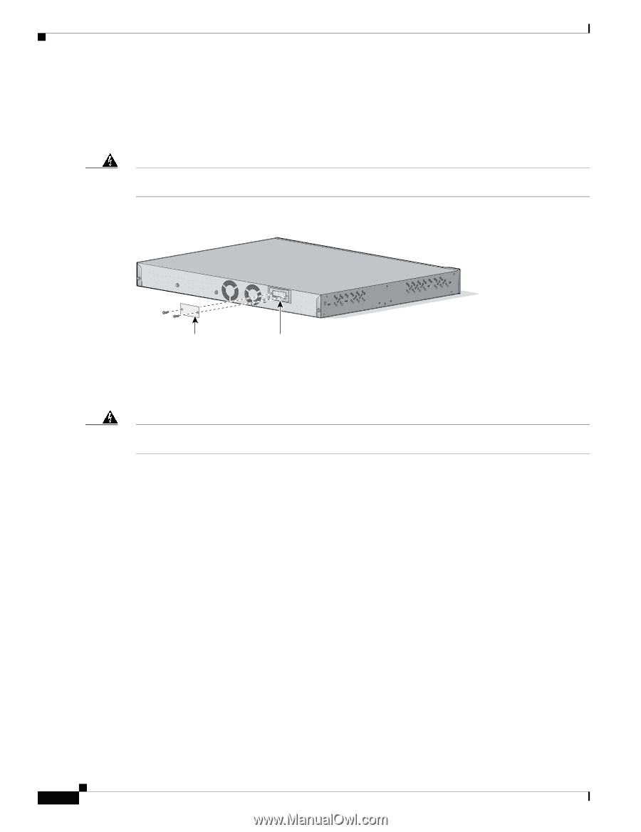
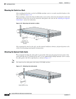
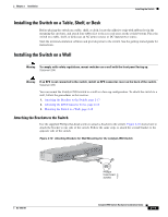
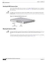
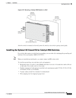
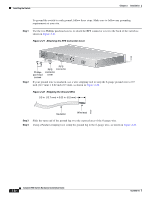
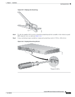
Installing the Switch Chapter 2 Installation Attaching the RPS Connector Cover If you are not using an RPS with your switch, use two number-4 Phillips pan-head screws to install an RPS connector cover to the back of the switch. (See Figure 2-19.) The pan-head screws are included in the accessory kit. Warning If an RPS is not connected to the switch, install an RPS connector cover on the back of the switch. Statement 265 Figure 2-19 Attaching the RPS Connector Cover 86310 RPS connector cover Mounting the Switch to a Wall RPS connector Warning To comply with safety regulations, mount switches on a wall with the front panel facing up. Statement 266 For the best support of the switch and cables, make sure the switch is attached securely to a wall stud or to a firmly attached plywood mounting backboard, as shown in Figure 2-20. 2-18 Catalyst 2950 Switch Hardware Installation Guide OL-6156-01
-
 1
1 -
2
-
3
-
4
-
5
-
6
-
7
-
8
-
9
-
10
-
11
-
12
-
13
-
14
-
15
-
16
-
17
-
18
-
19
-
20
-
21
-
22
-
23
-
24
-
25
-
26
-
27
-
28
-
29
-
30
-
31
-
32
-
33
-
34
-
35
-
36
-
37
-
38
-
39
-
40
-
41
-
42
-
43
-
44
-
45
-
46
-
47
-
48
-
49
-
50
-
51
-
52
-
53
-
54
-
55
-
56
-
57
-
58
-
 59
59 -
 60
60 -
 61
61 -
 62
62 -
 63
63 -
 64
64 -
 65
65 -
 66
66 -
 67
67 -
 68
68 -
 69
69 -
70
-
71
-
72
-
73
-
74
-
75
-
76
-
77
-
78
-
79
-
80
-
81
-
82
-
83
-
84
-
85
-
86
-
87
-
88
-
89
-
90
-
91
-
92
-
93
-
94
-
95
-
96
-
97
-
98
-
99
-
100
-
101
-
102
-
103
-
104
-
105
-
106
-
107
-
108
-
109
-
110
-
111
-
112
-
113
-
114
-
115
-
116
-
117
-
118
-
119
-
120
-
121
-
122
-
123
-
124
-
125
-
126
-
127
-
128
-
129
-
130
-
131
-
132
-
133
-
134
 |
 |