Cisco 2950 Hardware Installation Guide - Page 81
Connecting to GBIC Module Ports
 |
UPC - 746320454504
View all Cisco 2950 manuals
Add to My Manuals
Save this manual to your list of manuals |
Page 81 highlights
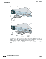
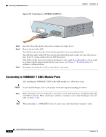
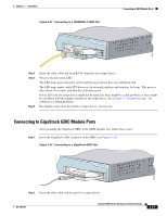
Chapter 2 Installation Connecting to GBIC Module Ports Connecting to GBIC Module Ports These sections describe how to connect to a GBIC module port. • Connecting to 1000BASE-X GBIC Module Ports, page 2-35 • Connecting to 1000BASE-T GBIC Module Ports, page 2-36 • Connecting to GigaStack GBIC Module Ports, page 2-37 For instructions about how to connect to the CWDM GBIC module ports, see the documentation that came with that GBIC module. For detailed instructions about installing, removing, and connecting to the GBIC module (the 1000BASE-X module, the 1000BASE-T module, the CWDM GBIC module, or the GigaStack module), see the GBIC module documentation. When connecting the ports on the Catalyst 2950G-24-EI-DC and Catalyst 2950ST-24 LRE 997 switches to other devices, follow these guidelines: Caution To comply with the intrabuilding lightning surge requirements, intrabuilding wiring must be shielded, and the shield for the wiring must be grounded at both ends. Caution The Catalyst 2950G-24-EI-DC or Catalyst 2950ST-24 LRE 997 switch is suitable only for intrabuilding or nonexposed wiring connections. Connecting to 1000BASE-X GBIC Module Ports Caution Do not remove the rubber plugs from the GBIC module port or the rubber caps from the fiber-optic cable until you are ready to connect the cable. The plugs and caps protect the GBIC module ports and cables from contamination and ambient light. After installing the 1000BASE-X GBIC in the GBIC module slot, follow these steps: Step 1 Remove the rubber plugs from the GBIC module port, and store them for future use. Step 2 Insert the SC connector in the fiber-optic receptacle (see Figure 2-40). OL-6156-01 Catalyst 2950 Switch Hardware Installation Guide 2-35
-
 1
1 -
2
-
3
-
4
-
5
-
6
-
7
-
8
-
9
-
10
-
11
-
12
-
13
-
14
-
15
-
16
-
17
-
18
-
19
-
20
-
21
-
22
-
23
-
24
-
25
-
26
-
27
-
28
-
29
-
30
-
31
-
32
-
33
-
34
-
35
-
36
-
37
-
38
-
39
-
40
-
41
-
42
-
43
-
44
-
45
-
46
-
47
-
48
-
49
-
50
-
51
-
52
-
53
-
54
-
55
-
56
-
57
-
58
-
59
-
60
-
61
-
62
-
63
-
64
-
65
-
66
-
67
-
68
-
69
-
70
-
71
-
72
-
73
-
74
-
75
-
 76
76 -
 77
77 -
 78
78 -
 79
79 -
 80
80 -
 81
81 -
 82
82 -
 83
83 -
 84
84 -
 85
85 -
 86
86 -
87
-
88
-
89
-
90
-
91
-
92
-
93
-
94
-
95
-
96
-
97
-
98
-
99
-
100
-
101
-
102
-
103
-
104
-
105
-
106
-
107
-
108
-
109
-
110
-
111
-
112
-
113
-
114
-
115
-
116
-
117
-
118
-
119
-
120
-
121
-
122
-
123
-
124
-
125
-
126
-
127
-
128
-
129
-
130
-
131
-
132
-
133
-
134
 |
 |