Cisco 2950 Hardware Installation Guide - Page 65
Installing the Optional AC Ground Kit for Catalyst 2950 Switches
 |
UPC - 746320454504
View all Cisco 2950 manuals
Add to My Manuals
Save this manual to your list of manuals |
Page 65 highlights
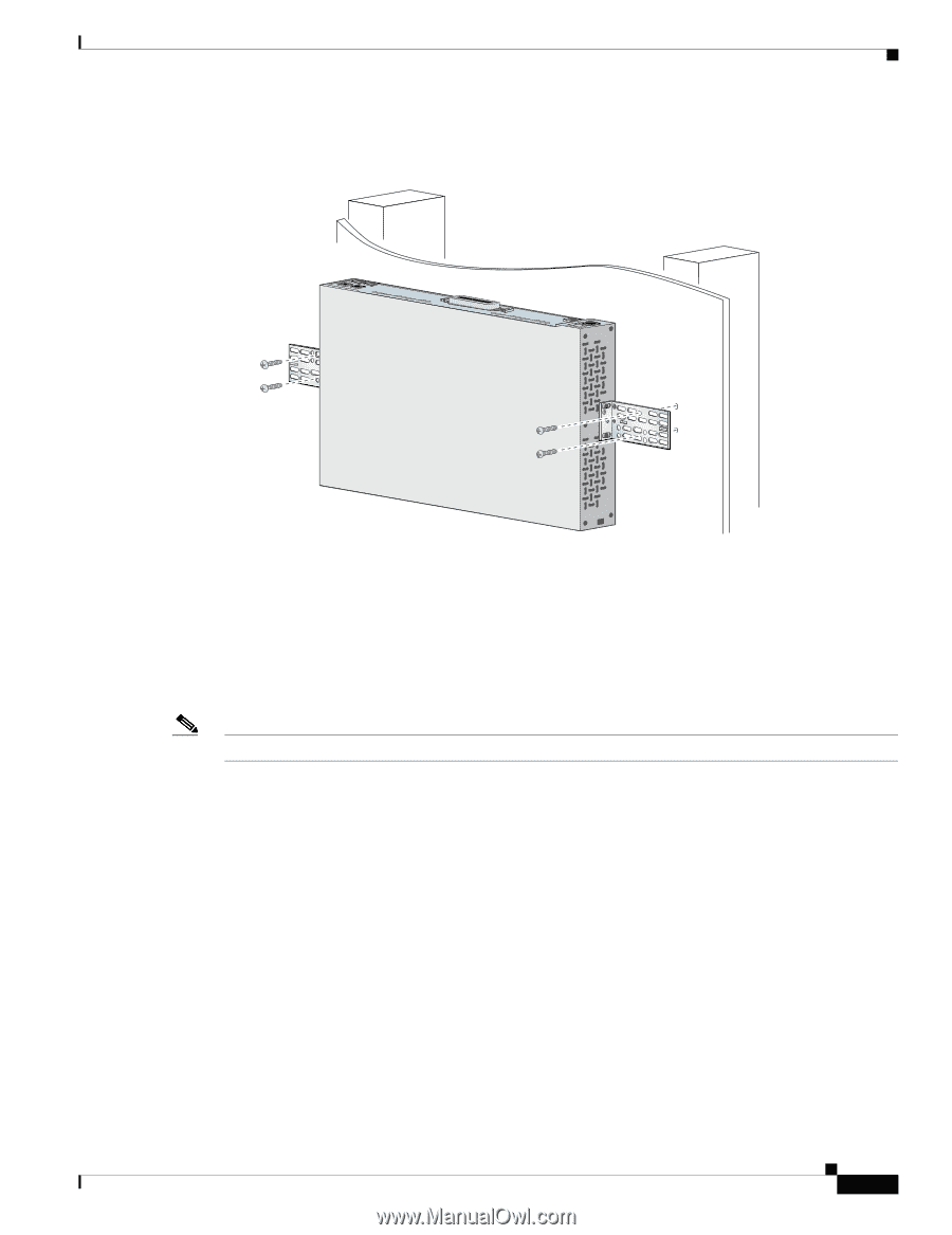
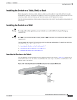
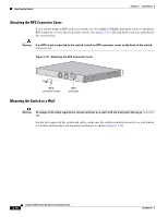
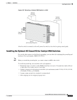
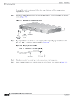
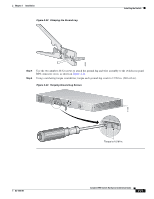
Chapter 2 Installation Figure 2-20 Mounting a Catalyst 2950 Switch to a Wall Vertical wall stud Installing the Switch Vertical wall stud Catalyst 2950 SERIES LRE 2A 2B 13 14 15 16 17 18 19 20 21 22 23 24 9 10 11 12 1.01A/000.-51A275/02-R06A00-TI2HN4ZM0GVO~DE SPEESDTAT RPS SYST CONSOLE 1 2 3 4 5 6 7 8 86317 User-supplied screws Face up wall mounting configuration After the switch is mounted on the wall, power the switch as described in getting started guide. Installing the Optional AC Ground Kit for Catalyst 2950 Switches For switches that require a two-hole lug for grounding, you can order a kit containing the ground lug and hardware (Cisco part number NEBS-LUG-3550=). Note When you install the ground-lug kit, you cannot connect an RPS to the switch. To install the ground lug, you need these tools and equipment: • Ratcheting torque screwdriver with a Phillips head that exerts up to 15 pound-force inches (lbf-in.) or 240 ounce-force inches (ozf-in.) of pressure • Panduit crimping tool with optional controlled-cycle mechanism (model CT-700, CT-720, CT-920, CT-920CH, CT-930, or CT-940CH) • 6-gauge copper ground wire (insulated or noninsulated) • Wire-stripping tool for stripping 6-gauge wires OL-6156-01 Catalyst 2950 Switch Hardware Installation Guide 2-19
-
 1
1 -
2
-
3
-
4
-
5
-
6
-
7
-
8
-
9
-
10
-
11
-
12
-
13
-
14
-
15
-
16
-
17
-
18
-
19
-
20
-
21
-
22
-
23
-
24
-
25
-
26
-
27
-
28
-
29
-
30
-
31
-
32
-
33
-
34
-
35
-
36
-
37
-
38
-
39
-
40
-
41
-
42
-
43
-
44
-
45
-
46
-
47
-
48
-
49
-
50
-
51
-
52
-
53
-
54
-
55
-
56
-
57
-
58
-
59
-
 60
60 -
 61
61 -
 62
62 -
 63
63 -
 64
64 -
 65
65 -
 66
66 -
 67
67 -
 68
68 -
 69
69 -
 70
70 -
71
-
72
-
73
-
74
-
75
-
76
-
77
-
78
-
79
-
80
-
81
-
82
-
83
-
84
-
85
-
86
-
87
-
88
-
89
-
90
-
91
-
92
-
93
-
94
-
95
-
96
-
97
-
98
-
99
-
100
-
101
-
102
-
103
-
104
-
105
-
106
-
107
-
108
-
109
-
110
-
111
-
112
-
113
-
114
-
115
-
116
-
117
-
118
-
119
-
120
-
121
-
122
-
123
-
124
-
125
-
126
-
127
-
128
-
129
-
130
-
131
-
132
-
133
-
134
 |
 |